
Sepp-Heindl-Str.5
83026 Rosenheim
Tel. 08031 / 24881
Fax 08031 / 24882
Manual
GLASGLOBAL® 18008
v7.42
5.4.2 Vertical glazing: Only message "Deflection too large“
5.5 Pre-assignment of glass, composite layer and SZR
7.6 Geometry in module Point fixing
7.6.3 Grid input for point fixing
7.6.4 Reacton forces for FEM point fixing
7.8 Geometry in the module Walk on
8.4 Save structure as product (only admin)
9.6.1 Tabular method (DIN 18008-4, attachment B)
9.6.2 Simplified verification procedure (DIN 18008-4, attachment C.2)
10.1.1 Wind loads according to EN 1991-1-4
10.1.2 Snow loads according to EN 1991-1-3
10.1.3 Wind- and Snow load in module Walk on
10.3.5 Wind/snow load -> indoor application
10.7.2 Superposition wind outside and inside
18.4 Display in program and printout
19.1.1 Suggestion module - filter total thickness
22.9.2 Toolbar in the position list
24.2 Product search on the main screen
24.4 Determining Rw from database
25 DIN 18008-6: Accessible and fall-through resistant glazing
25.2.3 Accessible/fall through
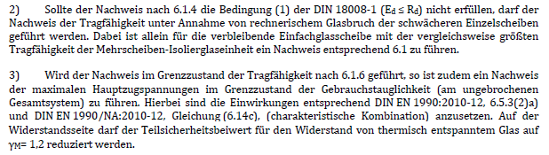
25.3.2 Verification of bearing capacity
25.3.3 Verification of load resistance and residual strength
26 General design approval Z-70.3-267 (DIBt)
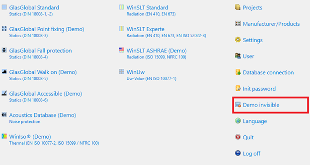
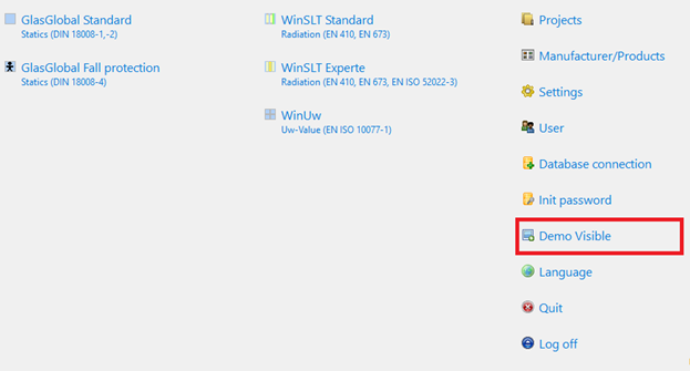
1 General – Hide Demo
With a new button it is now possible to show or hide demo modules.
2 Toolbar
![]()
Functions (from the left to the right)
|
New |
Clears the canvas and creates a new position, that is added to the recent project |
|
Search |
Opens the project search |
|
Save |
Saves the recent position including PDF as proof |
|
|
Prints the displayed report |
|
PDF export |
Exports the displayed report as PDF |
|
Calculate |
Accomplishes the calculation |
|
First step |
Goes back to the project details |
|
Step back Next step |
Previous processing step Next processing step |
|
Last step |
Goes to the result |
|
Help |
Activates this help |
|
Quit |
Quits the editor and saves the recent position |
3 Project data
The project’s specifications are made here.
Positions are summarized per project.

4 Navigation - processes
With a click in the navigation bar you get to the particular processes.
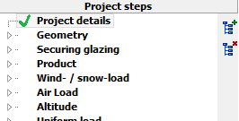
![]() Display of the sub-entries of the particular process
Display of the sub-entries of the particular process
![]() Display all sub-entries
Display all sub-entries
![]() Display only gists
Display only gists
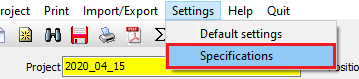
5 Defaults
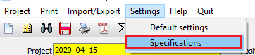
Menu „settings“à “Specifications” opens a window for the definition of Specifications.
![]()
The displayed specifications apply to the user. The change of the user saves the settings for the particular user.
![]()
Resets the specifications to default.
5.1 Characteristic strength
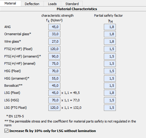
5.2 Limit of deflection
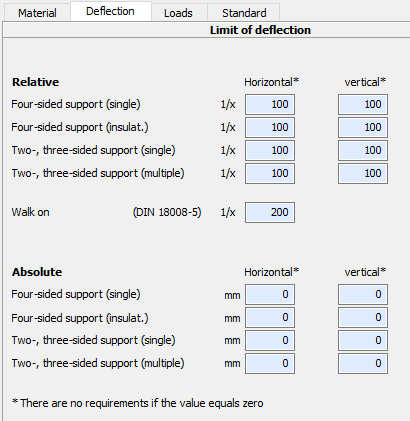
Zero means that the deflection is not relevant for the proof.
5.3 Loads
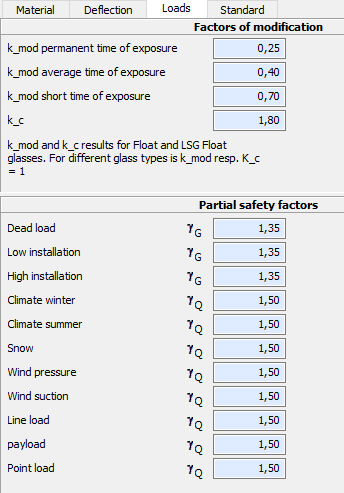
Here you can change factors of modification of the loads. They are preset with the values showed above.
5.4 Settings for the standard
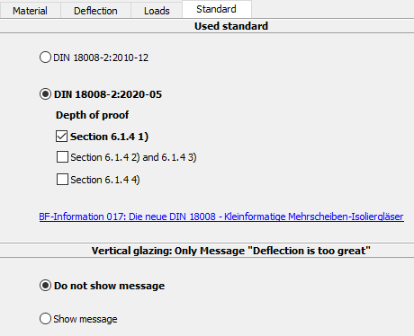
5.4.1 Standard used
The version of DIN 18008-2 used can be specified here.
For more information on the settings, see:
è DIN 18008-2:2020-05
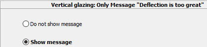
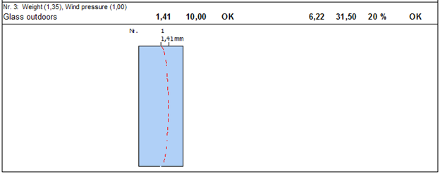
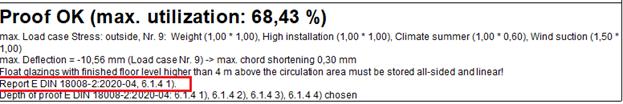
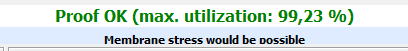
5.4.2 Vertical glazing: Only message "Deflection too large“
For vertical glazing, according to DIN 18008-2:2010-12 section 7.4 or
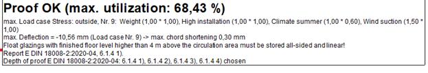
DIN 18008-2:2020-05 section 6.1.5, the decisive criterion is not the deflection criterion 1/100 of the span (or 1/65), but the remaining support width with existing chord shortening.
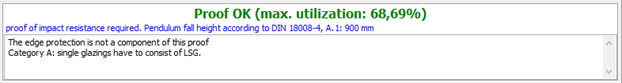
For this reason the standard display Proof OK appears with additional information on the maximum chord shortening:
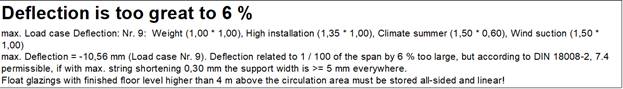
With the following setting, the note Deflection too large can still be displayed:
5.5 Pre-assignment of glass, composite layer and SZR
New default settings for basic glass, laminated layer and gas for SZR:
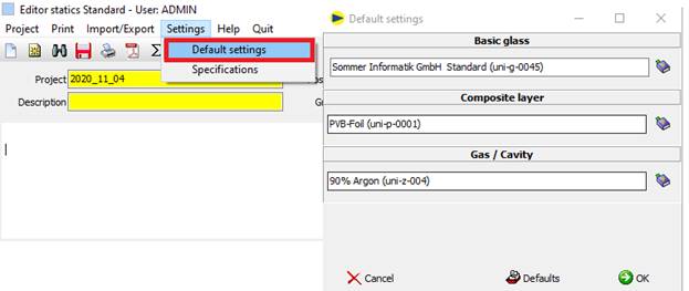
When creating a new position, the glass, composite layer and SZR are preset with the stored standard settings.
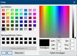
5.6 Colour for glass types
In the starter in the settings, a colour can be defined for each glass type.
Default: light blue.

- Previous settings on the General tab
- New tab "Colours“

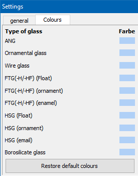
The colours appear in the respective programme modules and on the printout.
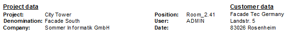
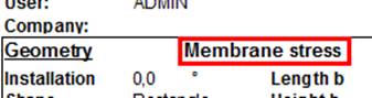
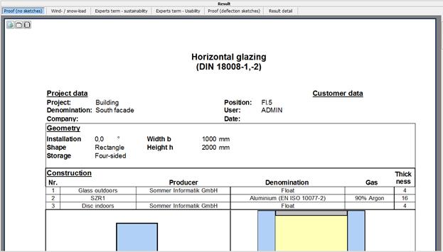
6 Project details
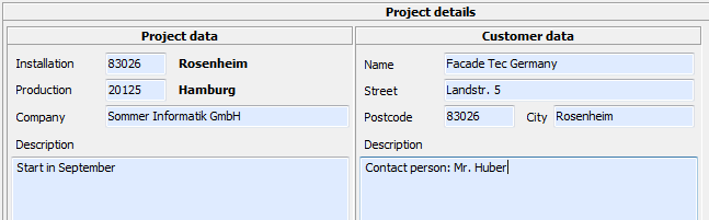
The data entered here appears in the heading of the proof:
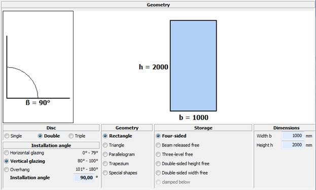
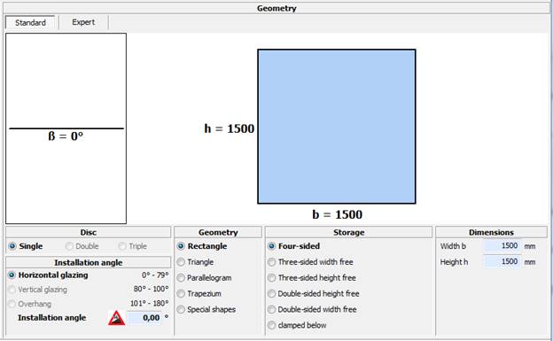
7 Geometry
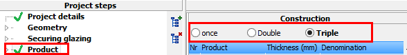
7.1 Pane
Number of panes.
The setting can also be modified under „product“:
7.2 Installation angle
Horizontal glazing Angle 0° to 79°
Walk On glazing only for horizontal angles
Vertical glazing Angle 80° to 100°
Securing glazing and distributed load are only available for vertical glazing.
Overhang Angle 101° to 180°
7.3 Shape(geometry)
Shape of the glass
Please note
- For distributed load only rectangle is available
- For membrane stress only rectangle is available
7.4 Support
Type of support
Please note
- “Clamped below“ available only for single panes
- Securing glazing according to category B is always “clamped below”
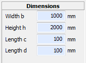
7.5 Measures
Depending on the form the different dimensions have to be quoted in mm.
7.6 Geometry in module Point fixing
7.6.1 Standard editor
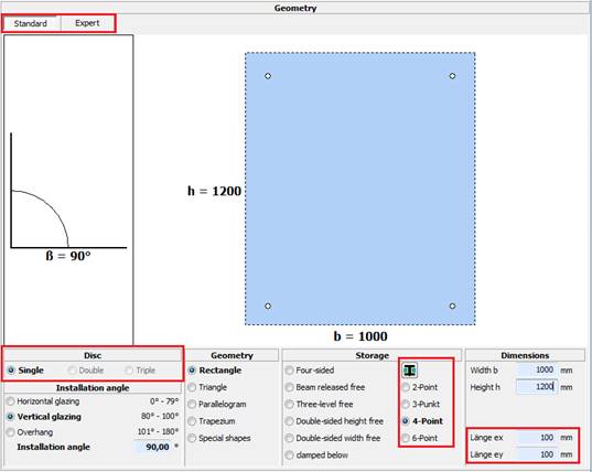
In module Point fixing the number and
position of the plate or clamp holders can be determined. There is a standard input editor and an expert editor
available.
For calculating a point-fixed disc, only single glazing is possible.
For the simple, symmetrical arrangement of plate holder in the disk, the number of holders will be selected from the list, and the distance (ex and ey) of the plate holder to the glass edge in X and Y direction can be set.
With the
symbol ![]() following window will
appear:
following window will
appear:
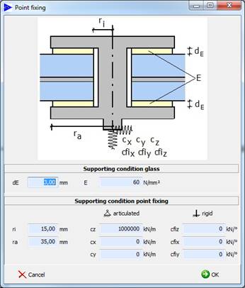
The characteristics of the intermediate
layer, marked yellow in the image, can be changed under support condition
glass. be changed are modulus of elasticity, and thickness the material.
These fields are preset with experience values.
The support conditions point fixing refers to the characteristics of the
point holder. The diameter of the bore and the clamping plate often differs
from the default values. The input fields cz,x,y contain the spring
stiffness of the point fixing.
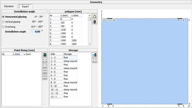
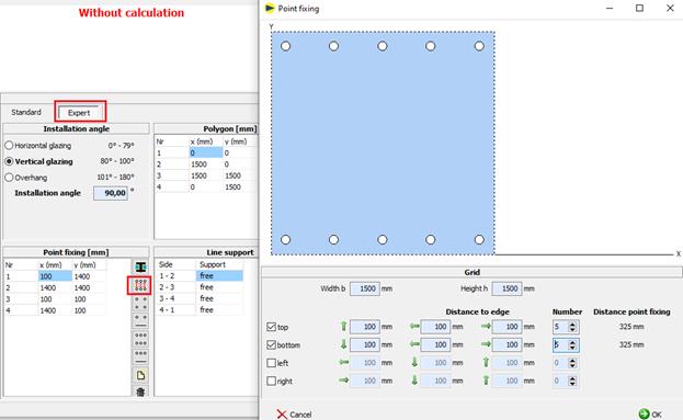
7.6.2 Expert
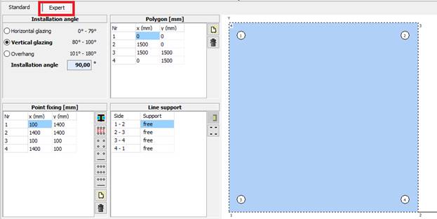
The Expert editor is separated in four parts:
1. Installation angle
2. Polygon
3. Storage
4. Point fixing
For 1. à The angle of installation can be set here
For 2. à Geometry of the glazing is defined here by the coordinates of the corners
For 3. à Here you can choose the support of the glazing between free, clamped and fixed
For 4. à Point fixings can be added with the icons, or by defining the coordinates of the drill holes. The point fixings can be put positioned at any place
New corners or point fixings can be added
with the symbol ![]()
To delete any position, press ![]()
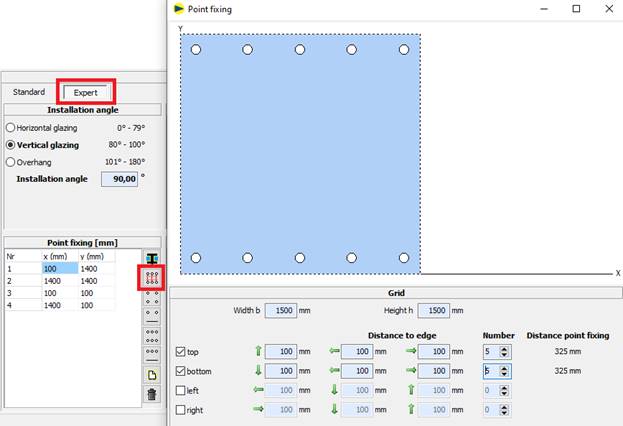
7.6.3 Grid input for point fixing
A grid input is available for positioning point fixing:
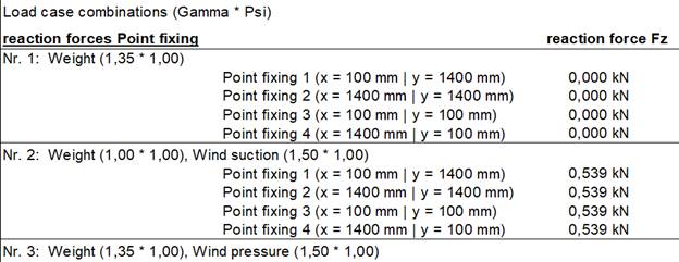
7.6.4 Reacton forces for FEM point fixing
In the GLASGLOBAL® FEM point support module, the output of the reaction forces Fz for the individual point fixing has been supplemented.
Settings
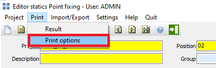
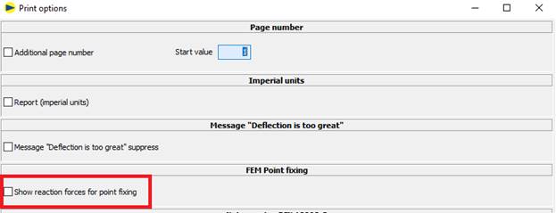
Output (last page printout proof)
7.7 Clamp mounting
Clamp mountings can be added with the
button ![]() (next to the field Storage).
(next to the field Storage).
The following window will be opened:
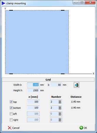
By selecting the sides top, bottom, left and right, clamps can be added on the glass edge. They will appear in the sketch. In the box e [mm], the distance of the clamp holder to the glass edge is defined. The number of clamp holder on one side can be changed via the arrow symbols. The distance of the clamp holder is displayed in the column Distance.
The geometry
of the clamp holder can be changed with the symbol ![]() in
following window:
in
following window:
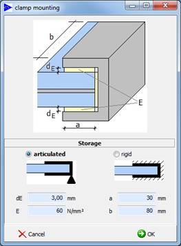
Input values here are:
dE = thickness of the interlayer from glass and clamp holder
E = E-modulus of the interlayer
a = length of glass in the clamp
b = length of the clamp holder
After you submit the clamp mounting, they will be added to the glazing.
The rim is divided into sections, and the support of the parts is set automatically. In the field Polygon you can see the coordinates of the coordinates, where the mounting changes.
7.8 Geometry in the module Walk on
7.8.1 Standard editor
The disk assembly may according to DIN
18008 part 5 consist only of VSG with at least three layers of glass. Therefore
under disc is only single glazing adjustable.
As installation brackets are values from 0 ° -79 ° for selection.
Geometry and storage are selected from the list, and the dimension is entered
in millimeters.
7.8.2 Expert editor
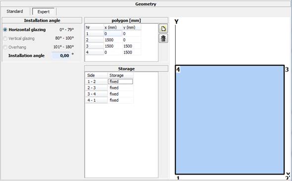
In the expert editor, the geometry of the
glazing can be entered with the coordinates of the corners.
The sides can be supported individually (fixed, free, clamped).
7.9 Membrane stress
![]()
The calculation with membrane stress is only available under the following requirements and approved according to DIN 18008-1:
· Add-on „membrane stress“ was activated
· Shape rectangle
· Four-sided support
· No taking into account shear coupling with laminated safety glass
The consideration of the membrane stress is
quoted in the proof: :
:
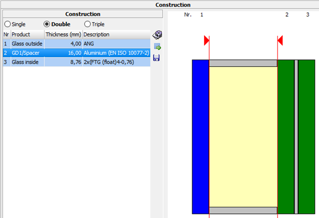
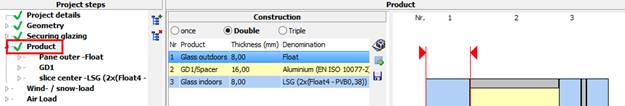
8 Define structure - product
![]()
Single glazing, double and triple insulating glazing
![]()
Edit of the marked layer (glass or GD)
Alternatively double-click on the line in list or the layer in the drawing
![]()
Search predefined products.
On choosing a product the whole structure will be replaced.
See chapter „8.3 Search product“
![]()
Saves recent structure as product
See chapter “8.4 Save structure as product (only admin) “
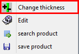
By right-clicking on a layer of the drawing you get this context menu.
The menu entries correspond to the points described above.
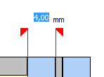
Additionally there is the possibility to modify the thickness of the marked glass by choosing the feature „change thickness“, whereby the new thickness can be typed in directly:
8.1 Define pane
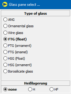
8.1.1 Type of glass
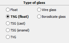
Set the type of glass here.
For laminated security glass only float, TSG (float) and TVG are available.
8.1.2 Single glazing
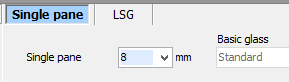
![]()
Specification of the thickness in mm
8.1.3 LSG
8.1.3.1 LSG symmetric
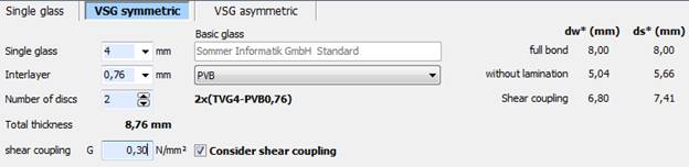
![]()
Specification of the thickness for the single glazing panes in mm
![]()
Thickness and type of interlayer
![]()
Number of glass panes and the consequent LSG structure
![]()
Substitute thicknesses for the calculation of the deflection (dw*) and the stress (ds*)
8.1.3.2 LSG asymmetric
With the new FEM-calculation it is possible to calculate asymmetric multilayer safety glass. The glazing can be made of max. 8 glass panes.
Therefore you just have to set the material and its thickness:
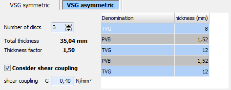
You can consider a shear coupling with asymmetric LSG, too. The thickness of the glass pane can be different by the factor 1.7 according to the standard. Otherwise the Thickness factor will be displayed red but a calculation is possible
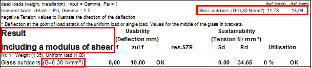
8.1.3.3 Shear coupling at LSG
![]()
When the hook is set, the specification of the shear coupling of the interlayer in N/mm² can be made.
Requirements:
· Only rectangle
· No membrane stress
· Number LSG panes = 2 in module Standard and Fall protection
· Up to 8 glass panes when calculating symmeric LSG
· For FEM-calculation: 8 glass panes with asymmetric structure possible
Please note
· Additional to “total bond” and “without bond” the LSG will be calculated “with thrust module”.
· The calculation “with thrust module” has no influence on the results of verification (OK, stress/deflection too big).
è In individual cases the user has to decide, if a fulfilled proof “with thrust module” replaces a not fulfilled proof „without bond“.
Output at the proof:
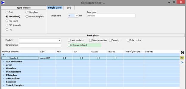
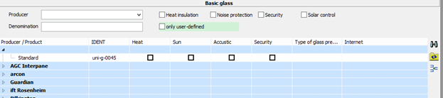
8.1.4 Basis glass
The basis glass functions among other things as definition of the producer.
At it the spectral data of the quoted basis glass will be used.
![]() Refreshes search result in accordance with justified filter
Refreshes search result in accordance with justified filter
![]() Resets filter and refreshes search result
Resets filter and refreshes search result
![]() Deletes marked basis glass (only user-defined, only admin)
Deletes marked basis glass (only user-defined, only admin)
![]() Edit basis glass (only user-defined, only admin)
Edit basis glass (only user-defined, only admin)
![]() Define new basis glass. The input will be made with the
following interface:
Define new basis glass. The input will be made with the
following interface:

Spectral data SLT
Link to existing basis glass, whose spectral data is supposed to be used for a later calculation in the WINSLT® module.
Type of glass preallocation
The type of glass will be pre-allocated with the value defined here on choice of this basis glass.
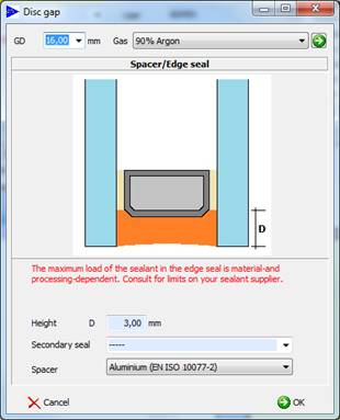
8.2 Define gap
![]()
Thickness GD in mm
![]()
Choice of the gas from predefined mixtures of gases
![]()
Height of the secondary seal in mm
![]()
This specification has no influence on the proof and acts only as an information.
![]()
For the calculation in the module WinUw the spacer settled here will be used.
8.3 Search product
![]() Refreshes search result in accordance with appointed filter
Refreshes search result in accordance with appointed filter
![]() Resets filter and refreshes search result
Resets filter and refreshes search result
![]() Deletes marked product (only user-defined, only admin)
Deletes marked product (only user-defined, only admin)
![]() Edit of the product data (only user-defined, only admin)
Edit of the product data (only user-defined, only admin)
![]() Replaces recent structure with marked product.
Replaces recent structure with marked product.
8.4 Save structure as product (only admin)
Using this feature the recent structure can be saved as a product.
SLT Product is available under WINSLT®
GlasGlobal Product is available under GLASGLOBAL®
IDENT Clear specific value for the product. Is specified by the program.
9 Securing glazing
Here the specifications for the proof of securing glazing will be made according to DIN 18008-4.
The chosen category appears on the first page of the proof:

9.1 Category A

Restrictions:
1. Single glazing has to consist of laminated security glass.
2. For the load side (attack side) of insulating glass units it is only permitted to use laminated security glass, toughened glass or laminated glass consisting of toughened glass.
3. Generally at least one pane of an insulating glass unit has to consist of laminated security glass.
4. Insulating glass units with toughened glass
at the attack side may contain roughly breaking types of glass (e.g. float
glass) immediately behind this pane, if there does not occur a breakage of
glass of the attack sided toughened glass pane at the pendulum load test.
9.2 Category B

9.2.1 Restrictions
1. Only laminated security glass usable
2. Only single panes
3. Support is always “clamped below“
9.2.2 Proof failure element
According to DIN 18008-4, 6.1.2 for category B the failure of a random element of the glass balustrades has to be additionally proved.
Please note:
· γm from specifications
· fk taking into account factors IAW DIN 18008-1, 8.3.8 and 8.3.9
· γG/Q = 1
· Laminated security glass is calculated without bond
· Only loading case distributed load will be proved
![]()
At the protected edges only the failure of a laminated security glass layer has to be proved. The proof of the remaining laminated security glass layer(s) will be accomplished with the quoted distributed load.
![]()
At the unprotected edges the failure of the whole element has to be proved.
· The neighboring pane, that must also carry the additional load resulting from the failure, has the same structure
· Proof for an efficient width beff= 0,5 m
· Proof with additional load qz = distributed load * widthfailure / beff
![]()
Neighboring element has to carry whole failure load
q(Proof) = qz * (1 + widthfailure/ beff)
![]()
Neighboring element has to carry only half the failure load
q(Proof) = qz * (1 + widthfailure/ (2 * beff))
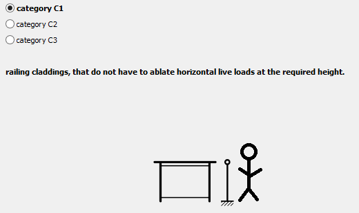
9.3 Category C1

Restrictions:
1. Only laminated security glass usable
2. Only single panes
9.4 Category C2

Restrictions:
1. All single glazing has to be accomplished with laminated security glass. Differing here from four-sided linear stored single glazing of the category C2 may be accomplished with toughened glass.
2. For insulating glass units of the category C2 for the load side only laminated security glass, toughened glass or laminated glass consisting of toughened glass has to be used.
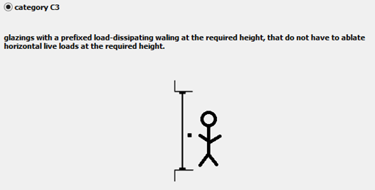
9.5 Category C3

Restrictions:
1. All single glazing has to be accomplished with laminated security glass.
2.
For glazing of the
category C3 concerning the usable glass products the requirements of category apply.
9.6 Proof of shock resistance
For the proof of the shock resistance the following procedure applies:
1. Proof according to DIN 18008-4, attachment B
2. Proof according to DIN 18008-4, attachment C.2, if attachment B is not fulfilled
3. If neither attachment B nor C.2 are fulfilled, an appropriate hint will be made under the result:
![]()
9.6.1 Tabular method (DIN 18008-4, attachment B)
Requirements:
· Geometry is inside of the admissible deviation of rectangular shape according to attachment B
· Min GD = 12mm
· Max GD = 20 mm
· No enameling
· The structure suits the values in DIN 18008-4, table B.1
Please note:
Please remember that the direction from attack to crash side is defined by the setting according to „distributed load“:
Output at the editor:
![]()
Output at the proof:
9.6.2 Simplified verification procedure (DIN 18008-4, attachment C.2)
Requirements:
· Geometry is inside of the admissible deviation from rectangular shape to attachment B
· Min GD = 12mm
· Only two-, three- and four-sided support -> not possible for category B
· Glass thicknesses: min. 1 x 6 mm, max. 2 x 19 mm
· Four-sided: maximal b = 2,0 m; h = 4,0 m
· Two-/three-sided: only cat. C, min. b = 0,7m; max. b = h = 2,0 m
Please note:
· γG/Q = 1
· Rd = kmod * fk / γm
fk without taking into account factors IAW DIN 18008-1, 8.3.8 and 8.3.9
kmod from table C.1 (DIN 18008-4)
γm = 1
· Laminated security glass will be calculated with total bond
· Proof of load capacity with point load P = 8,5 kN on an area of 20 x 20 cm in slab middle
Output at the editor:

Output at the proof (result, 1.side):
Output at the proof (after the loading cases, last side):

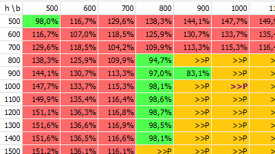
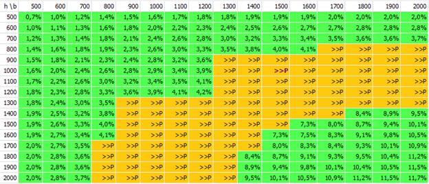
9.6.3 Size matrix
The proof of impact resistance DIN 18008-4 Appendix B or C.2 is now also taken into account in the size matrix.
If the ultimate and serviceability limit state design has been performed for a dimension, but not the impact resistance and residual capacity design, this is indicated by ">>P" for "pendulum impact"
10 Wind load and snow load
10.1 General
10.1.1 Wind loads according to EN 1991-1-4
Please note:
· Restriction to building up to a maximal height of 300 m and vibratory buildings (up to a height of 25 m (generally not prone to vibrations)
· Transgression probability: 2 %
· Return period: 50 years
Dependences:
· Geographic situation (wind zone), terrain conditions (terrain category) and wind velocity
· Layout of the building
· Height of the building
· Location of the subarea in the building
· Wind direction
· Opening in the building
Wind load
![]() in
kN/m²
in
kN/m²
With: ![]() = wind load in kN/m²
= wind load in kN/m²
![]() = aerodynamic coefficient (Depending on: area of the unit,
location of the unit in the building, relation between height and depth of the
building downwind, roof pitch, wind direction)
= aerodynamic coefficient (Depending on: area of the unit,
location of the unit in the building, relation between height and depth of the
building downwind, roof pitch, wind direction)
![]() = Dynamic pressure (Depending on: wind zone, terrain category,
datum level)
= Dynamic pressure (Depending on: wind zone, terrain category,
datum level)
![]() = Datum level (Depending on: Relation between height and width
of the building across the wind direction, installation height of the unit)
= Datum level (Depending on: Relation between height and width
of the building across the wind direction, installation height of the unit)
10.1.2 Snow loads according to EN 1991-1-3
Please note:
· Counts for edificial constructions, generally up to 1500 m above sea level
· Transgression probability: 2 %
· Return period: 50 years
Dependences:
· Place with the local clime and the topographic height
· Construction geometry
Snow load:
![]()
With: ![]() = Snow load in kN/m²
= Snow load in kN/m²
![]() = Shape parameter of the snow load (Describes the relation between
the amount of snow on top of the roof and the fallen amount of snow)
= Shape parameter of the snow load (Describes the relation between
the amount of snow on top of the roof and the fallen amount of snow)
![]() = characteristic value of the snow load on the ground in kN/m²
= characteristic value of the snow load on the ground in kN/m²
10.1.3 Wind- and Snow load in module Walk on
Calculations in de module GLASGLOBAL® Walk on do not consider wind or snow loads for the calculation.
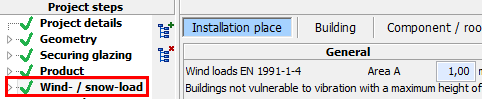
10.2 Open module
The invocation is made in the tree with “wind- / snow-load”:
Please note:
The in the following described features are only available, if the Addon “wind- / snow-load” has been activated. Otherwise the functionality is limited to a manual input of the resulting wind and snow loads.
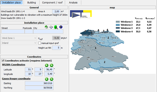
10.3 Installation place
10.3.1 Load influence area
The load influence area A will be preallocated corresponding to the glass dimensions typed in under “Geometry”.
DIN EN 1991-1-4, 7.2.1
The external pressure coefficients cpe for buildings and sections of buildings depend on the size of the load influence area A. They will be quoted in the decisive tables for load influence areas from 1 m² and from 10 m² as cpe,1 resp. cpe,10 that correspond to the building form.
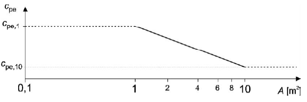
For 1 m² < A < 10 m² is valid:
cpe = cpe,1 - (cpe,1 -cpe,10) log10 A
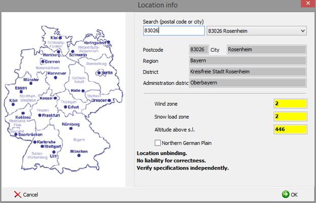
10.3.2 Location information
![]()
Sets street, post code and city from the project details and subsequently retrieves the related data in the location information.
![]()
Opens the post code register.Here, wind zone, snow load zone, local altitude above sea level and indicators for North German Plain will be detected.
![]()
Retrieves the quoted address with Google Maps
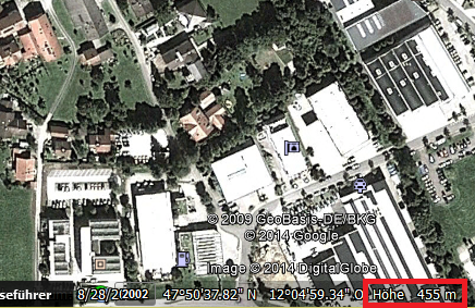
![]()
Displays the quoted address with Google Earth.
Requirement is the installation of Google Earth.
In Google Earth the local altitude above sea level can be read:
10.3.3 Terrain categories
Terrain category I High seas; Seas with at least 5 km free
area downwind; smooth flat land without obstacles
![]()

Terrain category II Terrain with hedges, single homesteads,
houses or trees, e.g. agricultural territory
![]()

Terrain category III Suburbs, industrial or commercial area;
woods
![]()

Terrain category IV Urban areas, where at least 15 % of the
surface is built on with buildings, whose average height exceeds 15 m
![]()

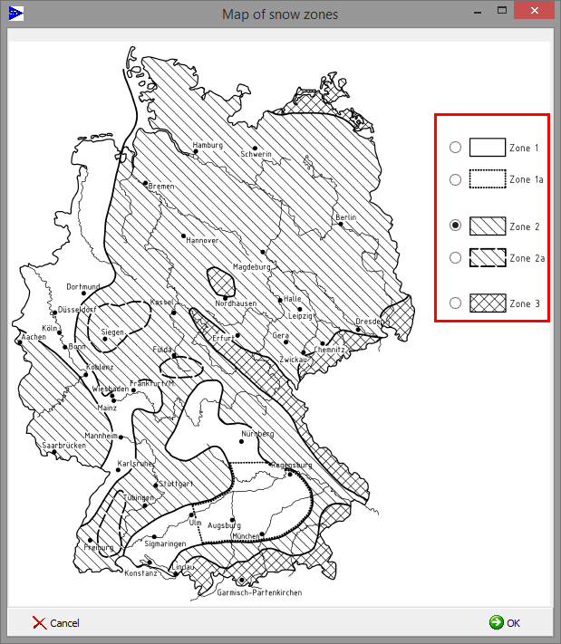
10.3.4 Snow load zones
![]()
Opens map to the manual choice of the snow load zone:
10.3.5 Wind/snow load -> indoor application
Under wind/snow loads a button "indoor application" has been added:

The button sets the wind and snow loads to "manual" and the loads to "0,00":
10.4 Buildings
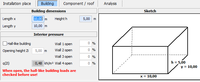
Building dimensions
Determination the building dimensions
Internal pressure
The internal pressure will only be considered, if it is a hall-like building. Please quote the amount of apertures on the walls 1 to 4 each time under “Wall open”.
With “Opening height Zi” you quote the reference height for the calculation of the internal pressure.
When you choose “Hall-like building”, there appears an additional result window for the internal pressure on the tab “Analysis”.
10.5 Unit/roof
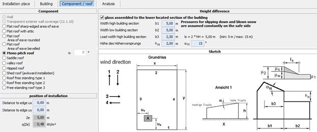
Unit
Here you choose the unit, in which the window will be built into.
The roof pitch will be set to the installation angle from “Geometry”.
Position of installation
Position of the glazing inside the unit
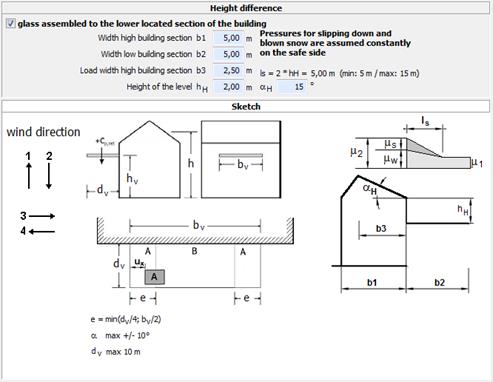
Jump in height
Specifications to the determination of the snow load at jumps in height at roofs according to DIN EN 1991-1-4, 5.3.6.
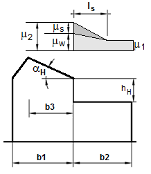
b1 Width tall part of the building
b2 Width low part of the building
b3 Width of the load from that the snow can slip down to the low part of the building
hH Height of the height difference
αH Roof pitch of the taller part of the building
ls Length of the drifting
ls = 2 * hH
whereby 5 ≤ ls≤ 15 m
µ1 = 0,8
µs Shape parameter for slipping snow
µw Shape parameter for snow taking account of wind
µ2 = µs + µw
Calculating µs
αH≤ 15°:
µs = 0
αH> 15°:
µshas to be calculated by means of an additional load of 50% of the largest entire snow load on the bordering roof pitch of the upper roof area. This entire snow load will be steadily set with µ1 = 0,8, also for roof pitches >30°, so that there will not be calculated a load, where several parts of the snow load are already slipped down.
It is accordingly clear: 0,5 * b3 * 0,8 * sK = 0,5 * µs * sK * ls
And here from: µs = 0,8 * b3 / ls
Calculating µw
HH≤ 0,5 m
µw = 0
HH> 0,5 m
µw = (b1 + b2) / 2hH≤ 2hH / sK - µs
Margin µ2
Generally: 0,8 ≤µ2≤ 2,4
For b2 ≤ 3 m: 0,8 ≤µ2≤ 2
For sK > 3,0 kN/m²: 1,2 ≤µ2≤ 6,45 / sK0,9
North Ger. Plain 2,3 * µ2≤ 4 which indicates µ2≤ 1,74
10.6 Add-On Porch
In this add-on canopies/porches according to DIN EN 1991-1-4 / NA, Attachment NA.V can be calculated.
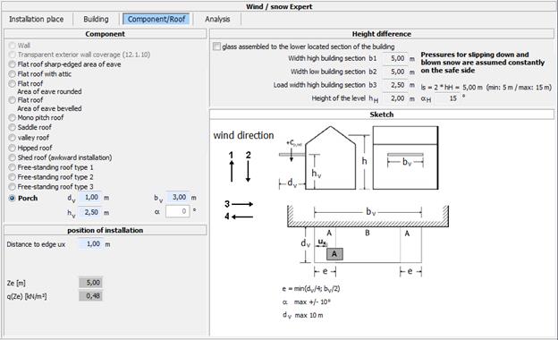
To obtain the maximum wind load with a
canopy, the edge distance must be set ux= 0.
The calculated wind load is independent of the wind direction and is equal for
all wind directions.
Intermediate values in DIN EN 1991-1-4 / NA, Table NA.V for the proportion
between hv / h and hv / dv (upward load) are
interpolated
To determine the snow load, the height difference can be considered.
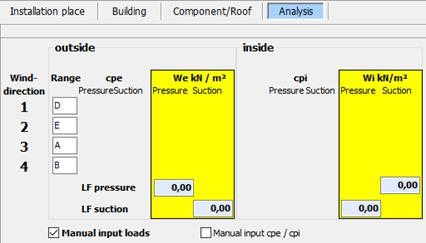
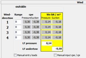
10.7 Analysis
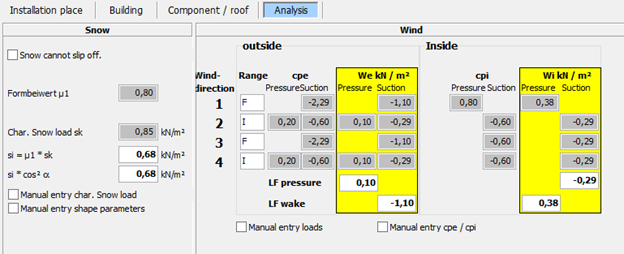
The parameters for the wind and snow loads will be summarized here.
Snow
si = µ * sk quotes the value for the snow load on the roof
si*cos²a snow load on the roof multiplied with the cos²a for considering the effective snow load of the roof
Wind
Resulting loads for the loading cases pressure and suction
10.7.1 Manual input
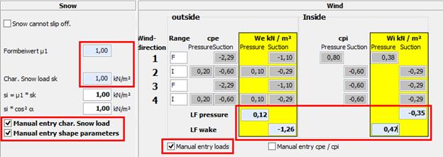
When the hooks at “Manual input” are set according to the foregoing values, the snow and wind loads can be typed in manually.
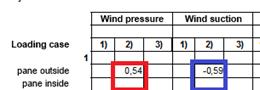
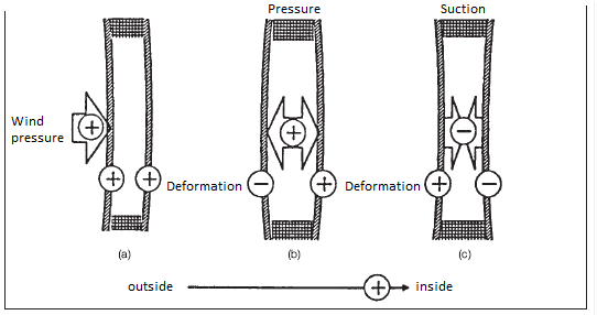
10.7.2 Superposition wind outside and inside
The superposition of outside and inside will be made according to following schema:
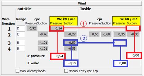
1. Loading case pressure
- Determination maximal pressure outside
- Determination related suction inside
2. Loading case suction
- Determination maximal suction outside
- Determination related pressure inside
Output at “Experts term”, example double:
11 Climate stress
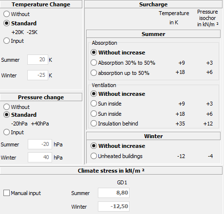
Unless specific data is used, the default
values will apply.
12 Altitude
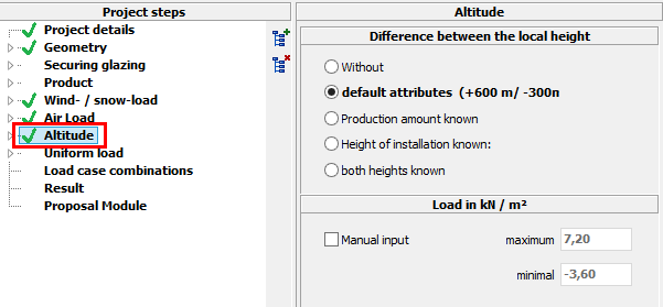
Without
No loads
Default attributes
Without knowing the production amount and installation height, the default attributes have to be used
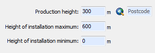
Producing height known
Determination of the production height with location info or postcode
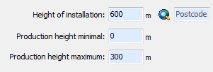
Height of installation known
Determination of the installation height with location info or postcode
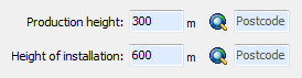
Both heights known
Determination of the production amount and installation height with location info or postcode
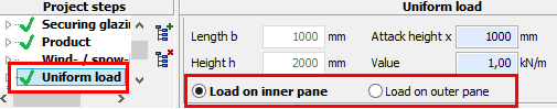
13 Uniform load
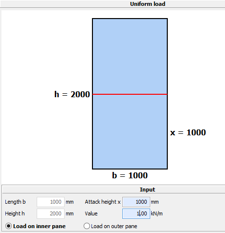
Restrictions
· Only for vertical glazing
· Only for rectangles
Entries
· Attack height in m
· Load in kN/m
· Side of the load application (inner or outer pane)
14 Payload
A definition of the payload is only necessary in the module Walk on. Here is a table in the standard (DIN EN 1991-1-1 / NA, Tab. 6.1DE), which differentiates areas by categories of use. These are:
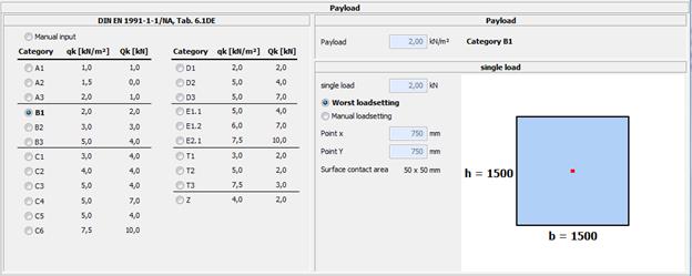
Values for payload can be changed by own values. The location, where the load attacks can also be changed.
You can look for the loads in following table:
|
Category |
Usage type |
Examples |
qk [kN/m²] |
Qk5) [kN] |
|
A1 |
Attic |
Accessible attic with heights up to 1.80m, not suitable as living space |
1,0 |
1,0 |
|
A2 |
Living-/Meeting room |
Ceiling with enough lateral distribution of the loads, rooms and corridors in residential buildings, hotel rooms and bed rooms in hospitals |
1,5 |
- |
|
A3 |
Like A2, but without enough lateral distribution of the loads |
2,03) |
1,0 |
|
|
B1 |
Office-/Work areas, Corridors, Hallways |
Corridors in office buildings, office areas, medical practice without heavy equipment, meeting rooms, small domestic animal stable |
2,0 |
2,0 |
|
B2 |
Cellar rooms in residential buildings, corridors/kitchen in hospitals, hotels, retirement homes, treatment rooms in hospitals, surgery rooms without heavy equipment. |
3,0 |
3,0 |
|
|
B3 |
Like B1 and B2, but with heavy equipment |
5,0 |
4,0 |
|
|
C1 |
Meeting rooms, Areas for gathering of people (Exception: in A,B,D,L defined categories) |
Areas with tables, e.g. kindergarten, classrooms, cafés, restaurants, reception rooms, staff rooms |
3,0 |
4,0 |
|
C2 |
Areas with fixed seating, e.g. in churches, theaters, cinemas, lecture halls, waiting rooms, congress rooms |
4,0 |
4,0 |
|
|
C3 |
Free passable areas, e.g. museum areas, exhibition halls, public entrance areas, hotels, corridors for areas which belong to category C1-C3 |
5,0 |
4,0 |
|
|
C4 |
Sport- and playgrounds, e.g. dance halls, sport halls, gymnastic and fitness rooms, stages |
5,0 |
7,0 |
|
|
C5 |
Areas for large gathering of people, e.g. concert halls, terraces, entrance halls, stance with fixed seating |
5,0 |
4,0 |
|
|
C6 |
Areas with regular use because of large gathering of people, stands without fixed seating |
7,5 |
10,0 |
|
|
D1 |
Salesroom |
Areas of salesrooms up to 50 m² area in residential and office buildings or similar |
2,0 |
2,0 |
|
D2 |
Areas in retail stores and department stores |
5,0 |
4,0 |
|
|
D3 |
Like D2, but with increased concentrated loads because of high storage racks |
5,0 |
7,0 |
|
|
E1.1 |
Storages, Workshops, Factories, Stables |
Areas in factories/workshops1) with low or middle activity |
5,0 |
4,0 |
|
E1.2 |
General storage areas, libraries |
6,02) |
7,0 |
|
|
E2.1 |
Areas in factories/workshops1) with middle or high activity |
7,52) |
10,0 |
|
|
T14) |
Stairs/Stair landing |
Stairs and landings in residential and office buildings, medical practice without heavy equipment |
3,0 |
2,0 |
|
T24) |
All stairs and landings which are not comply with T1 and T3 |
5,0 |
2,0 |
|
|
T34) |
Access and stairs of stands without fixed seating, which serve as escape route |
7,5 |
3,0 |
|
|
Z4) |
Balcony, Accesses, or similar |
Roof terrace, balcony, loggia |
4,0 |
2,0 |
|
1) Payloads in factories and workshops are considered predominantly static. In individual cases, often repetitive loads are classified according to the circumstances as not predominantly static loads. 2) These values are minimum values. In cases with higher loads, the higher loads apply. 3) For the transmission of loads in rooms with ceilings without adequate lateral distribution on supporting components, the specified value can de decreased by 0.5 kN / m². 4) With the combinations of actions, the effects of the use category of the building or building unit must be assigned. 5) If the proof of the local minimum carrying capacity is required (e.g. as in components without adequate lateral distribution of loads), the proof has to be performed with the characteristic values for the concentrated load Qk without superposition qk with the area load. The area for Qk includes a square with a side length of 50 mm. |
||||
15 Load case combinations
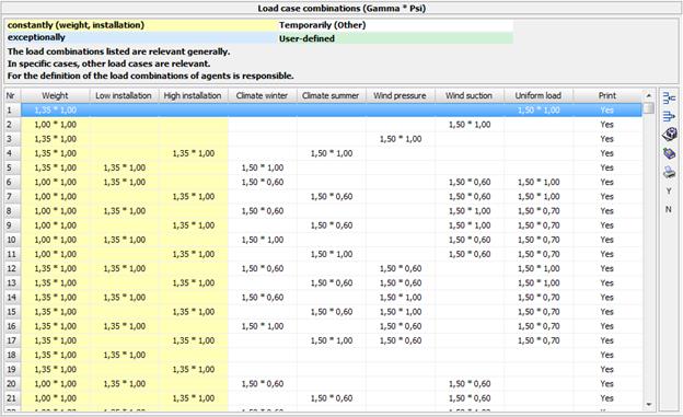
Display of the load cases for the procedure of furnishing proof:
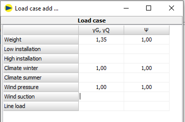
![]()
Adds a user-defined load case. The input will be made on the following interface:
![]()
Deletes the selected load case (only user-defined)
![]()
Edit marked load case (only user-defined)
![]()
Resets load cases to default
![]() (or double-click on line)
(or double-click on line)
Load case Print yes/no
![]()
Sets all load cases on Print = Yes
![]()
Sets all load cases on Print = No
15.1 Load case glass break
It is possible to define an own load case to calculate the case that an upper glass pane will break in an insulated glass and the shards will lay on the pane below. The load cases for a glass break are preset. There is also the possibility to define such a load case by the user. Therefore you have to select a load case B1 to B3:
Afterwards please click on the button ![]() to add a
new load case. A window to enter the psi-values will be opened.
to add a
new load case. A window to enter the psi-values will be opened.
The case “break of the outer pane” (DIN 18008-2, 5.8) is an out of the ordinary load (EN 1055-100, 9.4, Gl. 15).
![]()
With Ad = own weight of the shards, following load cases (preset in GLASGLOBAL®) are resulting (OW = own weight):
Height under 1000m
B1: OW + OW shards + snow (psi1=0.2) [+ wind (psi2=0)] kmod = middle (0.4)
B2: OW + OW shards + wind pressure (psi1=0.2) [+ snow (psi2=0)] kmod = short (0.7)
B3: OW + OW shards kmod = constantly (0.25)

Height over 1000m:
B1: OW + OW shards + snow (psi1=0.5) [+ wind (psi2=0)] kmod = middle (0.4)
B2: OW + OW shards + wind pressure (psi1=0.2) [+ snow (psi2=0.2)] kmod = short (0.7)
B3: OW + OW shards kmod = constantly (0.25)

15.2 North German lowlands
Another load out of the ordinary, north
German lowlands, can be set in the field wind and snow load. The load cases are
shown in the load case combinations with the designation “S1” – “S4”. They are
added automatically. Own load cases can be add with the symbol ![]() , like described in chapter 15.1.
, like described in chapter 15.1.

16 Result
Above the workspace the overall result is displayed:
The tab “Result” displays the preview of the detailed report.
The output will be made with following buttons in the toolbar:
![]() Output on printer
Output on printer
![]() Export as PDF file
Export as PDF file
Proof (without sketches)
Static proof including the list of the particular load cases without sketches
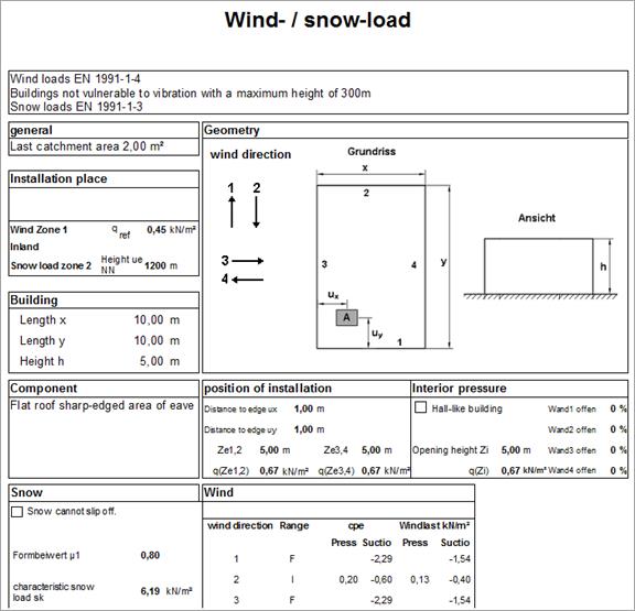
Wind / Snow load
The printout shows all important data for determination of those loads, as like the resulting wind pressure, suction and snow load
Experts term - sustainability
Detailed assembly of the particular load cases for stress analysis
Experts term - usability
Detailed assembly of the particular load cases for deflection analysis
Proof (deflection sketches)
Static proof including the list of the particular load cases, each time with deflection sketch
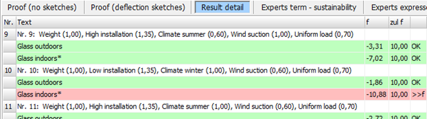
Result detail
Overview about the particular load cases
All green lines are in the admissible area, all red lines exceed the maximally admissible values.
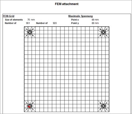
Proof (FEM Images)
If you calculate a project with the module Point fixing or Walk on, due to the FEM calculation, there is an additional result printout. This includes for each load case a color gradient image of stress and deflection.On the last page of this printout is a FEM-sheet that represents the main characteristics and the generated FEM grid.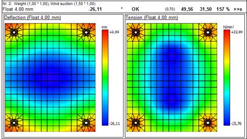
17 Additional results
17.1 String shortening
Please note:
· Will be calculated automatically
· Specification of the load case whereby the maximal deflection and therefore the maximal string shortening occurs.
· max. string shortening = 8 * fmax² / (3 * supporting width)
Output at the proof (result, 1. site):
![]()
17.2 Edge seal - edge load
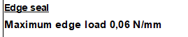
Here the maximum edge load for the edge seal is determined. GLASGLOBAL® determines the edge load on the safe side with the coefficient for rectangles. For square formats there would be lower edge loads.
18 DIN 18008-2:2020-05
In GLASGLOBAL® the proof has been updated according to white print DIN 18008:2020-05.
According to DIN 18008-2:2020-05, the partial safety factors on the exposure side and partly also on the reaction side may be reduced for multiple-glazed units (MIG) with a surface area of ≤ 2 m².
It can be assumed that this is a "rule of technology". However, the application must be discussed with the client.
18.1 Requirements
MIG up to 0,4 m²
or
MIG up to 2 m² with the following minimum thicknesses:
- 4 mm for monolithic single glasses
- 3 mm for monolithic single glasses made of TVG or ESG
- Laminated safety glass made of 2 mm single panes
- 2 mm for monolithic single panes of TVG or ESG in the inter-pane cavity of triple MIG
18.2 Settings
The specification of the underlying standard is defined in the specifications:
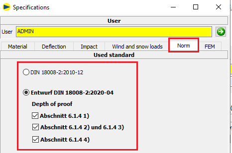
DIN 18008-2:2010-12
Previously used and currently still valid version of the standard
Draft DIN 18008-2:2020-05
White print of the standard. Its use should be agreed with the client.
The user can also determine the depth of verification:
![]()
![]()
![]()
![]()
The set detection depth is indicated in the result display and in the printout:
![]()
18.3 Flow chart
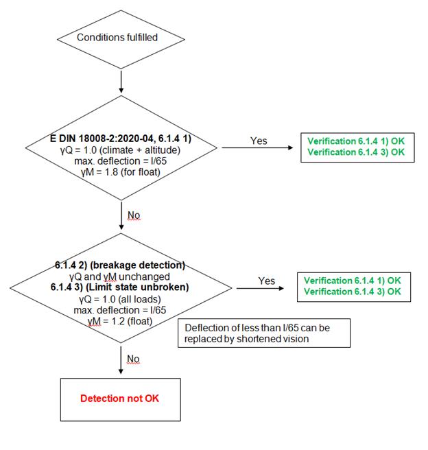
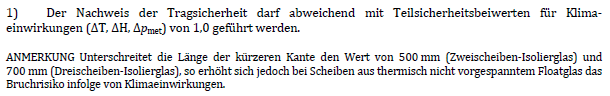
18.4 Display in program and printout
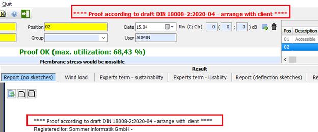
If calculations are carried out according to the new draft standard, this is clearly indicated in the mask and on the printout:
Notification upon verification according to 6.1.4 1)
Notification upon verification according to 6.1.4 2) and 6.1.4 3)
18.5 Glassthickness 2 mm
According to DIN 18008-1:2020-05, an increased partial safety factor γM must be applied for the thickness of the individual glass sheets of 2 mm.
è Thermally toughened glass (DIN 18008-1:2020-05, 8.3.6)
γM = 1.6 (instead of 1.5)
è Glasses without scheduled thermal tempering (DIN 18008-1:2020-05, 8.3.7)
γM = 1.9 (instead of 1.8)
The increase of the values for γM is taken into account by GLASGLOBAL®.
19 Proposal module
19.1 Glass thicknesses
Here the possible glazing thicknesses outside and inside will be detected, for whom the static proof with the recently lodged loads is fulfilled.
For LSG is the thickness of the individual disk specified.

![]()
Thicker pane preferably outside resp. on top
![]()
Both panes same thickness
![]()
Thicker pane preferably inside resp. below
![]()
Glass thicknesses, for whom the proof is not fulfilled, will not be diplayed
![]()
Take over glass thicknesses and accomplish proof
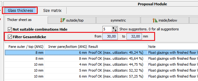
19.1.1 Suggestion module - filter total thickness
The suggestion module was extended by a filter for the total thickness. If the filter is activated, only superstructures whose total thickness, including SDR and composite layers, lies within the specified range are displayed.
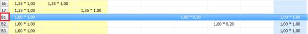
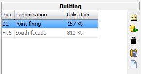
19.2 Size of Matrix
Here the results (utilization in %) for the recently lodged loads depending on width and height will be displayed.
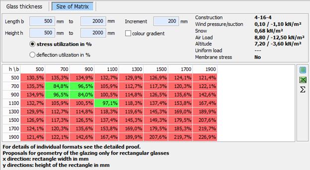
Values <= 100% green
Values> 100% red
![]()
Matrix for stress (load capacity)
![]()
Matrix for deflection (usability)
![]()
Colour gradient from green via orange to red
![]()
Colours only green and red
![]()
Take over dimensions and accomplish proof
![]()
Exports displayed matrix to Excel
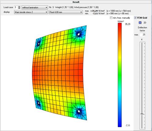
20 FEM graphic interface
In FEM images in the navigation, you can show the results of the calculation graphically when you calculate in Point fixing or Walk on module. Therefore we choose in the navigation from the list "FEM graphics".
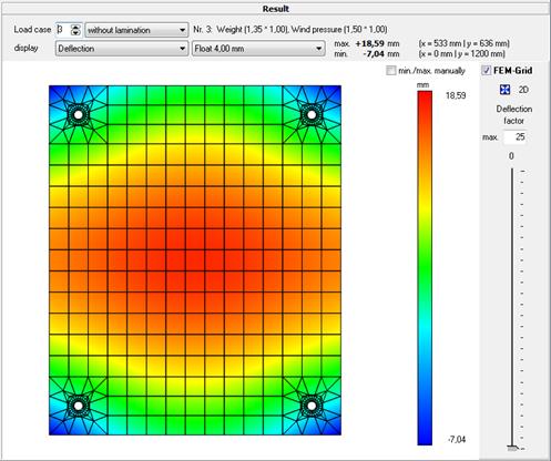
In the
header of the graphic interface the displayed load case can be selected. You
can choose between stress and deflection, and which disc you want to display.
Using the mouse wheel can rotate the graphic freely in any direction, and the
deflection can be increased by any factor.
Left mouse button: rotation
Right mouse button: move the pane
Mouse wheel: zoom in/out
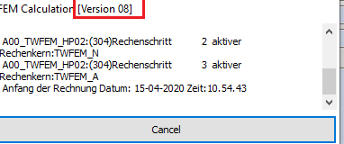
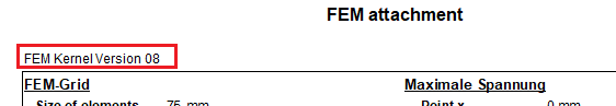
21 New FEM Kernel
In GLASGLOBAL® FEM a new calculation kernel was implemented.
So far version 05 was used here.
Now the used version can be defined in the defaults (default = 08).
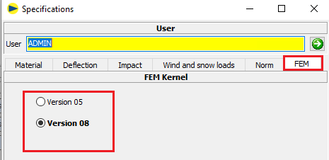
Version 08 leads to better results due to the finer meshing.
Version 05 Version 08
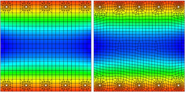
The version used is indicated in the calculation window and on the printout
21.1 Grid input point holder
A new grid input was defined for the positioning of point holders.
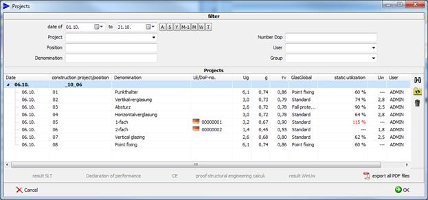
22 Project management
The position will be summarized for a project.
22.1 Change project
1.
Button ![]() in the toolbar
in the toolbar
2. Choice of the project using the following interface
![]() Refreshes search
result according to justified filter
Refreshes search
result according to justified filter
![]() Resets filter and
refreshes search result
Resets filter and
refreshes search result
![]() Deletes
marked project incl. all positions (only admin)
Deletes
marked project incl. all positions (only admin)
3. Confirm with OK
22.2 Change position
The change between the positions happens by clicking on the requested position on the list.
22.3 Generate new position
![]() Generates a new empty position
Generates a new empty position
22.4 Copy current position
![]() Generates a new position as a copy of the current position
Generates a new position as a copy of the current position
22.5 Delete position
![]() Deletes current position
Deletes current position
22.6 Rename project
![]() Changes the description for the current project for all
related positions:
Changes the description for the current project for all
related positions:

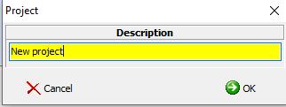
22.7 New project
![]() Generates a new project with quoted description:
Generates a new project with quoted description:
22.8 Copying entire projects
 A new function for copying
a project including all associated positions has been added in the project
search:
A new function for copying
a project including all associated positions has been added in the project
search:
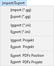
22.9 Export / Import
The following new export/import functions have been implemented:
-
Export Projekt
Exports selected items of a project to a ZIP fil
-
Import Projekt
Imports items from a ZIP file.
-
Export PDFs Projekt
Creates PDFs of selected items and merges them into one PDF if necessary.
22.9.1 Menü

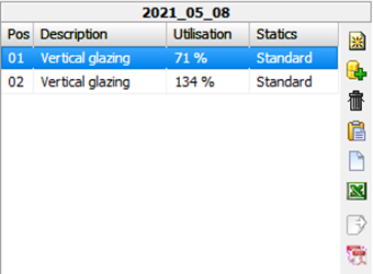
22.9.2 Toolbar in the position list
![]()

![]() Export Projekt
Export Projekt
![]() Export PDFs Projekt
Export PDFs Projekt
22.9.3 Export project
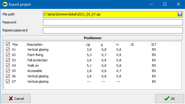
Input fields:
-
![]() File path (required
field):
File path (required
field):
Storage location of the ZIP file.
The user can select the file path via the button.
- Password (optional):
The contents of the ZIP file can be encrypted with a password.
-
Positions:
Positions of the project that are exported to the ZIP file,
preset: all positions
You can select or deselect all positions via the top tick. ![]()
At least one position must be selected.
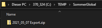
After clicking the button, ![]() SommerGlobal
creates a ZIP file with the selected items.
SommerGlobal
creates a ZIP file with the selected items.
22.9.4 Import project
Input fields:
-
File path (required field):
Location of the ZIP file
-
Password (optional):
Password for the ZIP file if its contents are encrypted.
-
Projekt (required field):
Name of the project under which the positions are added.
After clicking the button, ![]() SommerGlobal creates the items contained in the ZIP file in the
database.
SommerGlobal creates the items contained in the ZIP file in the
database.
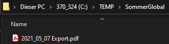
22.9.5 Export PDFs

Input fields:
-
File path (required field):
Storage location for PDF file(s). Via the button![]() , the user
can
, the user
can
either folder path for separate PDF files
![]()
or file
path for the merged PDF file
![]()
-
Positions:
Positions of the project whose PDFs are exported,
preset: all positions
You can select or deselect all positions via the top tick. ![]()
At least
one position must be selected
- Combine PDFs into one file
A fter clicking on the button ![]()
- SommerGlobal calculates each selected position,
- creates PDF file and
- merges the individual PDF files if the corresponding option is selected by the user.
Single PDF files:
![]()
Merged PDF file:
23 Sign rules
24 Sound database
24.1 Glossary
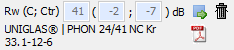
Evaluated sound insulation dimension R¬¬w
Rw is the sound reduction index of a building component, evaluated on the basis of a standard curve (to take human hearing into account).
It is given in dB.
Spectrum matching values C; Ctr
According to EN ISO 717-1, the spectrum adaptation values C and Ctr ("tr" for road traffic "traffic") denote a value in decibels that must be added to the singular Rw to take a specific sound spectrum into account.
The complete specification of the sound insulation of a component is given as follows:
Rw (C; Ctr) = 40 (-2; -5) dB
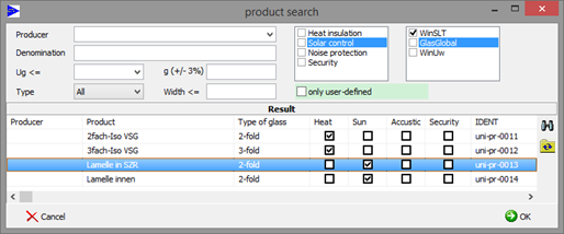
24.2 Product search on the main screen
The sound database can be called up in the main mask by clicking the following button:
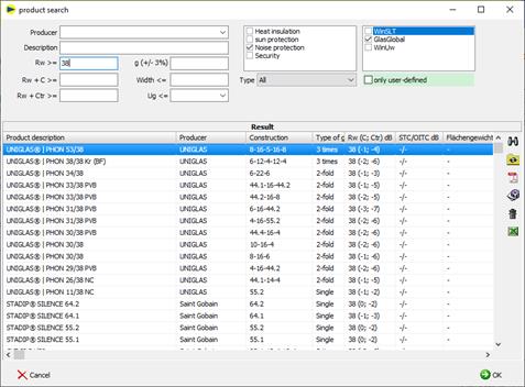
You will receive a list of the deposited products for sound insulation:
![]()
è Setting the filters and searches
è „Rw", "Rw + C >=" and "Rw + Ctr >="
The required sound insulation value is taken as the minimum value and all products with a sound insulation value higher or equal to the specification are listed.
![]()
è Shows deposited PDF, e.g. test certificate, expert opinion
è Button only available if PDF is available
![]()
è Edit product
è Only for custom products and editors is Admin
![]()
è Delete product
è Only for custom products and editors is Admin
Selection of the product
è Select the marked product by clicking "OK
è or double click on product line
è Transfer of the sound insulation values and the product name to the main mask of the editor
Sort
è When you click on a heading, the list is sorted according to the column clicked on
24.3 Product search
To select a product, proceed as follows:
è Call up product search:
è The product search is displayed
è
The available functions are described under
point 2
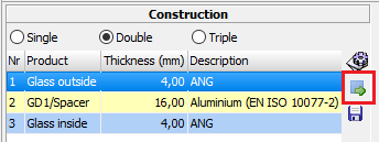
24.4 Determining Rw from database
When searching the database, the type of gas in the SDR is not taken into account.
To determine the sound insulation value for an existing glass structure from the database, proceed as follows:
è Call up product search
![]()
è
Display of the products that match the current
structure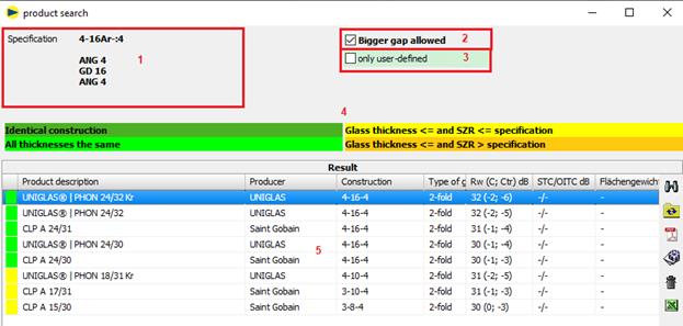
For products to be displayed with a sound insulation film (e.g. "..|PHON..NC"), the design must also include a sound insulation film (e.g. Trosifol® SC Monlayer or Multilayer) in the specification.
1 Default = current structure
2 Larger SDR allowed: products with a larger SDR (orange) are also displayed. Check is off by default because the comparison is on the insecure side.
3 User-defined only displays only products that have been saved by the user.
4 Legend for the individual colors
The nature of the gas in the SDR is not taken into account.
![]()
The structure is identical to the specification, i.e. all thicknesses (glass, SDR and composite layers) are the same.
![]()
All thicknesses (glass and SDR) match. The composite layers are not taken into account. For laminated safety glass, monolithic panes of the same thickness are also determined without taking the composite layers into account.
Only monolithic panes of the same thickness are determined for monolithic panes.
![]()
At least one glass thickness or SDR is less than the specification. The composite layers are not taken into account.
![]()
At least one SDR is greater than the specification and the glass thicknesses are less than or equal to the specification. The composite layers are not taken into account.
5 Search result
è Select a product and confirm with OK
è
Existing values can be deleted with the button![]()
è
A manual entry is made directly into the input
fields: ![]()
24.5 Printout
è Result
Rw is only shown on the printout if a value has been stored:
![]()
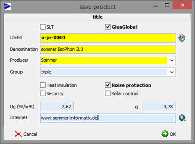
24.6 Define product
User-defined products are stored as follows:
è Define pane structure
è Save the current slice structure as a product:
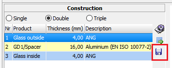
è Enter product data
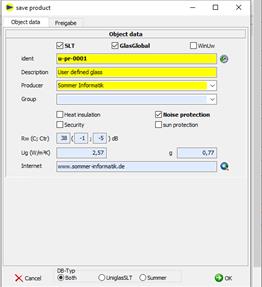
![]()
![]() Link an
existing document in the database to the product
Link an
existing document in the database to the product
![]() Modify an
existing document in the database
Modify an
existing document in the database
![]() Delete a
document link
Delete a
document link
è Store documents (PDF) (optional)
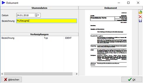
![]() load
document
load
document
![]() delete
document
delete
document
![]() Save
document as
Save
document as
Note
The documents are saved as copies in the database "SiProjekte.gdb".
The original file remains unaffected.
25 DIN 18008-6: Accessible and fall-through resistant glazing
25.1 General
According to DIN 18008-6 the addon "Betretbar" was implemented in GLASGLOBAL®.
In DIN 18008-6 the following types of glazing are distinguished:
- Accessible glazing
Glazings which can be entered for maintenance work (e.g. cleaning)
- Crash-proof glazing
Glazings that are not accessible to pedestrians and are located near areas that can be entered for maintenance work.
25.2 New project
The Addon for DIN 18008-6 is called up in the main mask via the following button:
In the following, only the entries that differ from the basic module (18008-1, -2) are described.
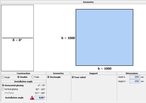
25.2.1 Geometry
The geometry is limited to rectangular discs supported on all sides.
According to DIN 18008-6, values from 0° to 100° are possible for the installation angle.
25.2.2 Product
Specifications according to DIN 18008-6:
- The regulations of DIN 18008-2 or 3 apply
- Use of wired glass is excluded
- ESG or VSG should be used for the top pane of multiple-pane insulating glass
25.2.3 Accessible/fall through
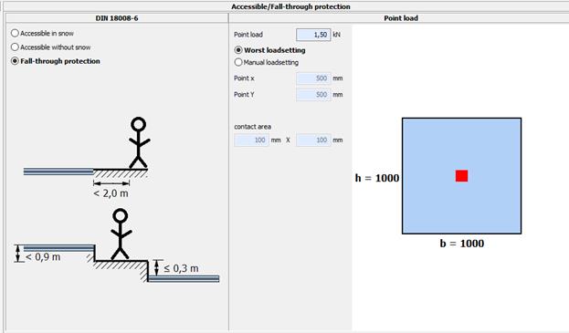
Accessible with snow
Glazing should also be walked on in snow
Single load is superimposed with snow load when the load-bearing capacity is verified (Ψ0 = 1.00)
Accessible without snow
Glazing should not be stepped on when there is snow
Single load is not superimposed with snow load when the load-bearing capacity is verified
Fail-safe
Glazings that are not accessible to pedestrians and are located near areas that can be entered for maintenance work.
Single load
According to DIN 18008-6, the static proof
for a substitute person load of 1.5 kN distributed over a contact area of 100
mm X 100 mm must also be provided.
25.3 Printout
25.3.1 Inputs
The entries for accessible or fall-through resistant glazing are made on the first page:
![]()
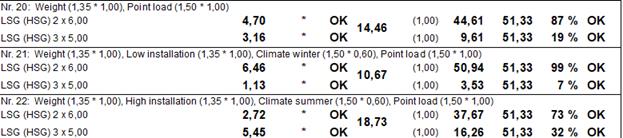
25.3.2 Verification of bearing capacity
Following the standard load cases, the load cases for the individual load are displayed. It is not necessary to check the serviceability here.
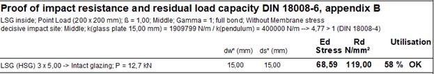
25.3.3 Verification of load resistance and residual strength
The verification is carried out according to DIN 18008-6, Appendix B.
If the mathematical verification is not provided,
the results text refers to the necessity of an experimental component test.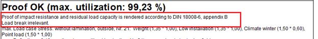
The results of the verification according to Annex B are given at the end of the printout.
In the case of multiple-pane insulating glass, only the bottom pane is always to be verified here.
.
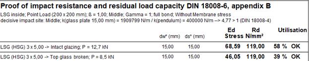
Lower pane
è Intact glazing: P = 12.7 kN (basic energy 225 Nm)
è Upper disc broken: P = 8.5 kN (basic energy 100 Nm)
25.3.3.1 Crash-proof glazing
Lower pane
è All VSG layers are applied
è P (basic energy 225 Nm) for installation angle = 0° (horizontal)
è P (basic energy 100 Nm) for installation angle 90° ± 10 ° (vertical)
è Intermediate values (0° to 80°) are interpolated linearly
è Multi-pane insulating glass, ratio thickness upper to lower pane
è ≤ 1.5: Point load with 50% of the base energy
è > 1.5: Point load with 100% of the base energy
è
25.3.3.2 Addition under "Break “
For the category "Accessible", the load case for "Weight + single load" was added under "Break":
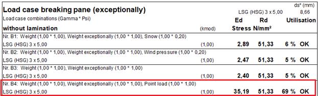
For "fall-through proof" no individual load must be verified under "breakage".
25.3.4 Result display
The result display has been changed as follows:
If the verification of load resistance and residual load capacity according to DIN 18008-6, Appendix B is not fulfilled, this is now displayed more clearly:
25.3.5 Size matrix
The verification of impact resistance and residual load capacity according to DIN 18008-6, Appendix B is now also taken into account in the size matrix.
If the ultimate and serviceability limit state design has been performed for a dimension, but not the impact resistance and residual capacity design, this is indicated by ">>P" for "pendulum impact".
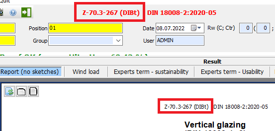
26 General design approval Z-70.3-267 (DIBt)
According to the general type approval number Z-70.3-267 (DIBt)
https://www.dibt.de/pdf_storage/2021/Z-70.3-267%281.70.3-9%2121%29.pdf
values for kmod deviating from DIN 18008-1 may be used for linearly mounted glazing made of multiple-pane insulating glass.
1. Menu -> Settings -> Defaults
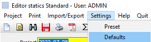
2. Set settings:
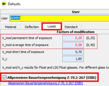
3. A note on the changed kmod- values is made in the results overview:
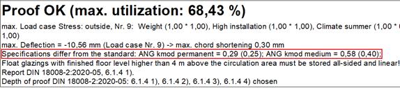
4. A note appears on the printout and in the editor:
Notes
è The processor is responsible for defining the kmod- values
è Only for extreme cases (almost no temperature stress) applies:
kmod(medium) = 0,43
Example: SZR temperature differences in summer < approx. 2 K and in winter > approx. -4 K. For this case, the stress from air pressure change can become greater than from temperature change. Otherwise applies kmod(medium) = 0,58.
è The adjusted values in the defaults remain until they are changed again.
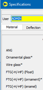
27 FTG -H and -HF
1. Designation FTG
o without addition
o or with addition H (hot storage)
o or with addition HF (hot storage and external monitoring)Default: keine
2. Only visible for "FTG" (float), FTG (ornament) and FTG (enamel)Keine
3. Effect on Rd.
4. Appears in the designation on the printout
5. Specifications: "(-H)" changed to "(-H/-HF)".
On the printout:
![]()
28 Links
Sommer Informatik Homepage:
GLASGLOBAL® Homepage:
FEM Grafic interface: