 Sommer Informatik GmbH
Sepp-Heindl-Str.5
83026 Rosenheim
Tel. 08031 / 24881
Fax 08031 / 24882
Manual
WINSLT®
1.2 Text input Glass structure
1.2.2 Defining the glass structure
6 Edit structure of the layers
6.7 Improved handling in the editor
9 Declaration of performance and CE
9.3 Settings LE / CE (only admin)
9.3.1 Declaration of performance - General
9.3.2 Declaration of performance - characteristics
9.4 Declaration of performance - new version EN 1279:2018
9.5 Settings printing (only admin)
10.9.2 Toolbar in the position list
11.1.1 Change ventilation factor
11.1.2 Explanations for the ventilation factor
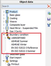
11.3 Change boundary condition
11.4 Create slat (Slat module)
11.5.1 Generate silkscreen glass
11.5.2 Silkscreen glass in VSG
12.1 Structure of an import file
13.2.2 Selection of the extraction method
13.2.3 Indication of the coating thicknesses
13.2.4 Basis glass and composite layer (only when coating to composite layer)
13.2.5 Indication to core data of the coating resp. composite layer
15.2 Product search on the main screen
15.4 Determining Rw from database
16 Vacuum insulation glazing (Add-on)
17 Products no longer produced
18 CIE L*a*b* (DIN EN ISO 11664-4)
19 Extension of colour rendering index (EN 410)
21.2.1 Internal convective heat transfer coefficient hci
1 General
1.1 Hide demo
A new button makes it possible to show or hide demo modules as preferred.
1.2 Text input Glass structure
1.2.1 Default settings
Adjustment ofthe presetting for base glass, coating, laminated layer and inter-space:
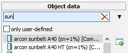
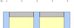
1.2.2 Defining the glass structure
1. Input of the text to search for the object data
![]()
2. Conclude with Enter
3. The structure is created with the materials from the default settings
2 Toolbar
![]()
Functions (from the left to the right)
|
New |
Clears the working space and generates a new position, which is added to the current project |
|
Search |
Opens the project search |
|
Save |
Saves the current position incl. PDF file for result, LE und CE |
|
|
Prints the open position |
|
Export PDF file |
Exports the displayed report as PDF file |
|
Calculate |
Accomplishes the calculation |
|
Undo |
Undoes the last process step |
|
Restore |
Undoes the last “Undo”-action |
|
Call the help |
Invokes this help |
|
Quit |
Quits the editor and saves the current position |
3 Project data
The specifications for the project will be made here.
Positions will be summarized each project.

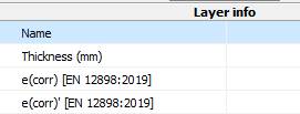
4 Option emissivity
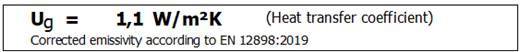
For the determination of the corrected emissivity, an option for the version of EN 12898 used has been added:
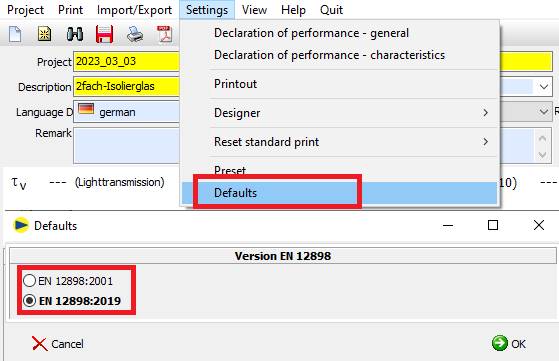
The version of EN 12898 used can be seen
- Under "shift info
In the printout
5 Object data materials
|
|
In this area all materials and products that are visible for the user are displayed, grouped in accord with type / producer / group.
When double-clicking on a material the material will be added to the current structure. Alternatively you can drag the material to the requested position in the structure.
|
5.1 Icons in the tree
![]() Product (Stored
structure, layer sequence known)
Product (Stored
structure, layer sequence known)
![]() Glass pane (Stored
structure, layer sequence not known)
Glass pane (Stored
structure, layer sequence not known)
![]() Basic glass (uncoated
glass)
Basic glass (uncoated
glass)
![]() Coating (to gap/air)
Coating (to gap/air)
![]() Coating to composite
layer
Coating to composite
layer
![]() Weave between two
composite layers
Weave between two
composite layers
![]() Composite layer
Composite layer
![]() Gap (ventilated and
non-ventilated)
Gap (ventilated and
non-ventilated)
![]() Boundary condition
Boundary condition
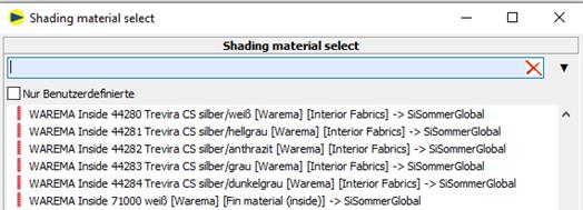
![]() Shading material
Shading material
![]() Slat (created from
shading material)
Slat (created from
shading material)
![]() Silkscreen glass
Silkscreen glass
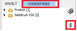
5.2 Search materials
Using the search box you can filter the tree. Now only the materials are displayed, whose denomination contains the quoted search word
5.3 Folder structure
Any folder structure can be created for the user-defined materials.
![]() Create new folder
Create new folder
![]() Rename folder
Rename folder
![]() Update tree
Update tree
![]() Dissolve folder
"unsorted" and move to folder per material type
Dissolve folder
"unsorted" and move to folder per material type
Folders are automatically deleted as soon as they are empty and the tree is updated.
5.4 Material
![]() Edit material
Edit material
![]() Copy and edit material
Copy and edit material
![]() Delete material
Delete material
5.5 Creating custom materials
To create a new material, select the folder in which you want to place the material and then click one of the following buttons:
|
|
Creates the current setup as a product in the selected folder.
|
|
|
Opens the dialogue for importing spectral data sets.
|
|
|
Opens the Extractor and creates the corresponding materials.
|
|
|
Opens the Gas Mixer
|
|
|
Create new vacuum
|
|
|
Creates a new boundary condition
|
|
|
Opens the dialogue for creating a new slat
|
|
|
Opens the dialogue for creating a silkscreen glass |
5.6 Search product
Button opens window with available products:
![]() Refreshes search result in
accordance with appointed filter
Refreshes search result in
accordance with appointed filter
![]() Resets filter and refreshes search result
Resets filter and refreshes search result
![]() Deletes marked product
(only user-defined, only admin)
Deletes marked product
(only user-defined, only admin)
![]() Edit of the product data (only
user-defined, only admin)
Edit of the product data (only
user-defined, only admin)
![]() replaces the current structure by marked product
replaces the current structure by marked product
5.7 Data import
By the use of this feature spectral data can be imported.
See chapter “9 Import spectral data” for a detailed
description of this feature.
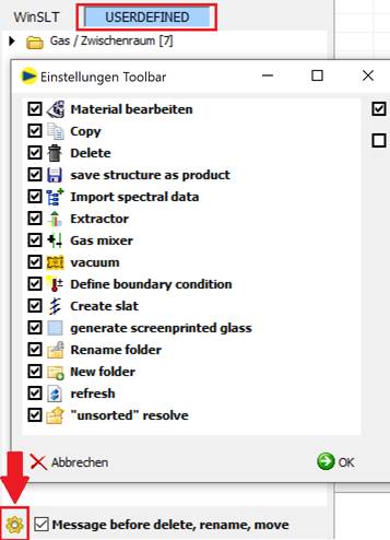
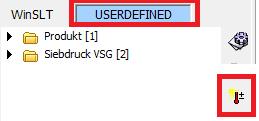
5.8 Settings toolbar
For the display of the buttons in the toolbar under Custom a setting has been added:
6 Edit structure of the layers
In this area the current structure can be displayed and edited.
6.1 Paste layer
Double-click in the tree
Layer will be attached at the structure inside (right)
Drag & Drop
Layer will be added at the structure in a random position
Possible hint
For certain coatings there are combination specifications for the basis glass that should be used. On pasting such a coating an appropriate hint is made:
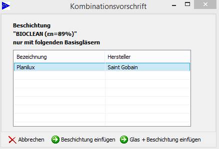
![]()
Only coating (without basis glass) will be pasted
![]()
Coating and marked basis glass will be pasted
6.2 Relocate layer
1. Mark layer with the left mouse button or in the window “coat sequence”
2. Drag the marked layer to the requested position.
(Alternative: Arrow keys left/right)
|
|
|
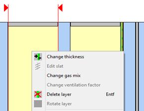
6.3 Delete layer
For the deleting of a layer you mark it by left-clicking (multiple selection with pressed “Ctrl” key) and hit the “Del”.
|
|
|
Alternatively to this you mark the layer by left-clicking and subsequently activate the context menu by right-clicking. Choose “delete layer” for deleting it.
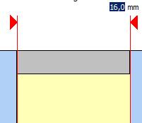
6.4 Change layer thickness
For changing the thickness of a basis glass, a PVB film or a gas, double-click the appropriate layer with the left mouse button.
|
|
Above the layer marked like this appears the currently appointed thickness that may be overwritten with the requested value. |
|||
|
|
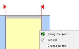
Alternatively you can choose a layer by left-clicking and invoke the context menu by right-clicking. By choosing “change thickness” now you can type in a random thickness (explained above). |
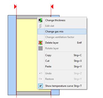
6.5 Change gas mix
The default setting when pasting an interstice filled with gas is 100% gas with a filler loading of 90%. Air-filled interstices are occupied with 100% air and 100% filler loading by default.
|
|
By left-clicking you choose a layer and by right-clicking you invoke the context menu. When choosing “change gas mix” a new window opens up, where you can define a custom gas mix. |
|
|
Please type in your own gas mix here. It will only be changed here in the component range, not in the material database.
In this example the resulting mix consists of 90% argon, the rest is filled up with air.
|
|
|
Filler loadings over 90% are only possible using the expert editor. The limitation of the filler loading is a recommendation by the producer, since windows with filler loadings over 90% are rarely produced. |
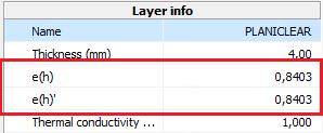
6.6 Layer composition
|
|
This area displays a detailed description of the coat sequence.
|
|
|
Under “layer composition” the physical properties of the currently chosen layer is displayed. |
|
|
P.r.n. a hint for the marked layer will be displayed here. |
6.7 Improved handling in the editor
The following adjustments have been implemented for editing in the editor:
1. after removing (Del-key) a layer, the remaining layer at the same position is automatically marked
2.  After inserting a new layer, the new layer is automatically marked.
3. Turn the marked layer with the space bar
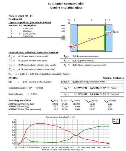
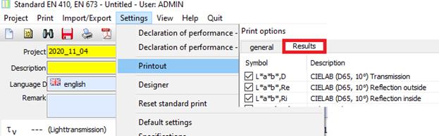
7 Result
The most important calculation results are displayed above the structure.
![]()
The tab “Result” displays the preview of the detailed report.
The output will be made using the following buttons in the toolbar:
![]() Output on printer
Output on printer
![]() Export as PDF file
Export as PDF file
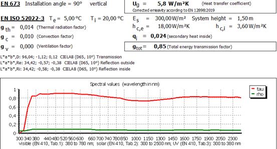
8 gtot EN ISO 52022-3
 Under EN ISO 52022-3, the
designation of the total energy transmittance has been changed to
"gtot". Under EN 410, the designation remains unchanged at
"g" in conformity with the standard.
Under EN ISO 52022-3, the
designation of the total energy transmittance has been changed to
"gtot". Under EN 410, the designation remains unchanged at
"g" in conformity with the standard.
9 Declaration of performance and CE
The producer must allocate a declaration of performance according to article 6 of the “BauPVo” for each building product that has to be provided with a CE mark when placing it on the market.
The declaration of performance quotes the performance of a building product related to the essential features of a building product concerted with the underlying harmonized technical specifications.
Basis for the declaration of performance is a technical documentation that has to be made by the producer that contains a description of the elements in conjunction with the required system for valuing and verifying the constancy of performance.
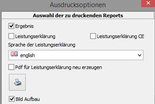
9.1 Preview
Using the tab “declaration of performance” / “CE” you receive a preview for the declaration of performance / CE.
The output happens by using the following buttons in the toolbar:
![]() Output on printer
Output on printer
![]() Export as PDF file
Export as PDF file
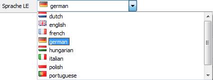
9.2 Set language
The choice of the language is made using the dropdown-menu “language LE” and pertains for the declaration of performance as well as for the CE tagging:
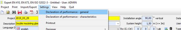
9.3 Settings LE / CE (only admin)
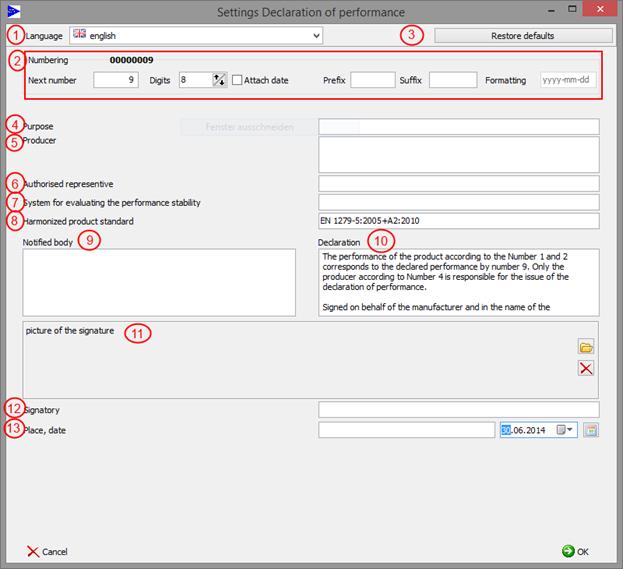
9.3.1 Declaration of performance - General
|
No. |
Required specifications in the declaration of performance |
Specifications |
|
1 |
Language |
For each language the data is saved separately |
|
2 |
Numbering |
Setting of the continuing number of the declaration of performance across languages |
|
3 |
Restore defaults |
Restores the values for the justified language to “factory setting“àGeneral and characteristics |
|
4 |
Designated purpose(s) of the building product according to usable harmonized technical specifications |
Here the specific purpose hast to be quoted. |
|
5 |
Name, registered trade name or brand and contact address of the producer according to article 11 paragraph 5 |
Enrollment of the full contact data, brand name or trade name of the producer’s building product |
|
6 |
P.r.n. name and contact address of the authorizer, that is commissioned to settle the tasks according to article 12 paragraph 2 |
Enrollment of the full contact data of the possible authorizer according to BauPVO art. 2 |
|
7 |
System or systems for valuing and checking the constancy of performance of the project according to attachment V
|
Here there has to be endorsed system 1+, system 1, system 2+, system 3 or system 4 |
|
8 |
In case of declaration of performance concerning a building product that is captured by a harmonized norm |
Specification of the harmonized product standard |
|
9 |
In case of declaration of performance concerning a building product for which a technical valuation has been issued |
Specification of the notified position (Please note: The company Sommer Informatik GmbH is no notified spot
|
|
10 |
Declaration |
Declaration of the right issuance of the declaration of performance according to BauPVO |
|
11 |
Picture of the signature |
To this field the signature can be loaded digitized (all common formats are supported) |
|
12 |
Signatory |
Name and feature of the person responsible for the creation of the declaration of performance |
|
13 |
Place, date |
The date can be selected using the drop-down arrow |
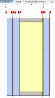
9.3.1.1 Declaration of performance – Presentation of pane structure
For the declarationof performance the settings for the representation of the pane structure have been extended:
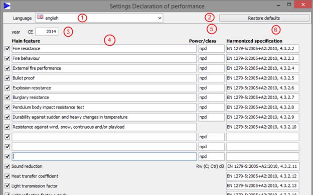
9.3.2 Declaration of performance - characteristics
|
1 |
Language |
For each language the data is saved separately |
|
2 |
Restore defaults |
Restores the values for the justified language to “factory settings” General and characteristics |
|
3 |
Year CE |
Year for issue on CE |
|
4 |
Main feature |
List of the primary features for the declared purpose |
|
5 |
Power/class |
Power of the building product for the listed main features |
|
6 |
Harmonized specification |
Harmonized technical specification (number and date of issuance, p.r.n. reference number) |
Using the hooks at the left edge the particular characteristics for the issuance on the declaration of performance can be blended or hidden .
Three additional lines are available for the manual input of further characteristics.
9.4 Declaration of performance - new version EN 1279:2018
Due to the new version of EN 1279:2018, the default settings for the preparation of the declaration of performance have been adjusted.
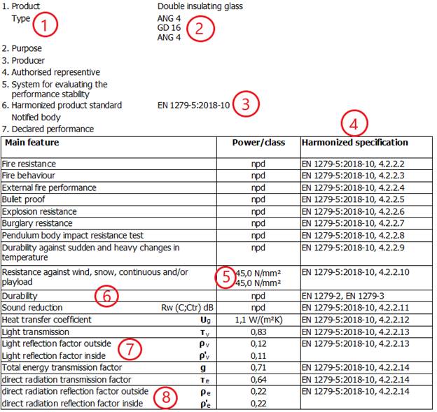 The adjustments in detail:
1 Numbering has been adjusted
2 Glass construction was added under "Type"
3 Update of the harmonized product standard
4 Updating of harmonized specifications
5 Indication of bending stiffness under "Resistance..." instead of glass structure
6 Durability was added as user input
7 Light reflection factor inside has been added
8 direct radiation reflection inside has been added
The following properties are still optionally available, but are hidden when the default settings are set according to the new version of the standard:
![]()
![]()
To set up the new version of the declaration of performance, the default settings are restored.
Please note that the existing settings will be overwritten.
 |
9.5 Settings printing (only admin)
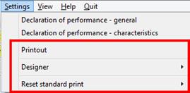
9.5.1 Print
In this dialogue the settings for the subsequent printing of result, declaration of performance and CE indicator are made.
9.5.2 Designer prints
Opens the designer for adapting the reports for declaration of performance and CE.
Adapted report data are saved in the subfolder “report” with denomination “LeistungsErkl_USER.fr3” resp. “LeistungsErklCE_USER.fr3”.
At the next print this adjusted report data will be used.
9.5.3 Restore standard print
Restores the report data for declaration of performance resp. CE to “factory settings”. Thereby the existing report data will be renamed with “_USER” so that at the next print once more it is possible to access the original reports.
10 Project management
The positions are combined into one project.
Project, position and denomination correspond to the project data:
10.1Change project
1.
Button ![]() in
the toolbar
in
the toolbar
2. Selection of the projects with the following interface
![]() Refreshes search result according to selected filter
Refreshes search result according to selected filter
![]() Resets filter
and refreshes search result
Resets filter
and refreshes search result
![]() Deletes marked project incl. all positions resp. the marked project
(only admin)
Deletes marked project incl. all positions resp. the marked project
(only admin)
3. Confirm with OK
10.2Change position
The change between the position is made by clicking on the requested position on the list.
10.3Generate new position
![]() Generates a new empty position
Generates a new empty position
10.4Copy position
![]() Generates a new position as copy of
the current position
Generates a new position as copy of
the current position
10.5Delete position
![]() Deletes current position
Deletes current position
10.6Rename project
![]() Changes the denomination for
the current project for all related positions:
Changes the denomination for
the current project for all related positions:
10.7New project
![]() Generates a new project with
quoted designation:
Generates a new project with
quoted designation:
10.8Copying entire projects
A new function for copying a project including all associated positions has been added to the project search function:
10.9Export / Import
The following new export/import functions have been implemented:
-
Export Projekt
Exports selected items of a project to a ZIP file.
-
Import Projekt
Imports items from a ZIP file.
-
Export PDFs Projekt
Creates PDFs of selected items and merges them into one PDF if necessary.
10.9.1 Menu

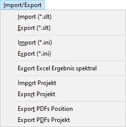
10.9.2 Toolbar in the position list
![]()
![]() Export Projekt
Export Projekt
![]() Export PDFs Projekt
Export PDFs Projekt
10.9.3 Export Projekt
Input fields:
-
![]() File path (required
field):
File path (required
field):
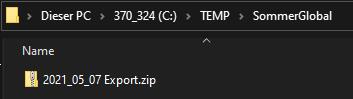
Storage location of the ZIP file.
The user can select the file path via the button.
-
Password (optional):
The contents of the ZIP file can be encrypted with a password.
- Positions:
Positions of the project that are exported to the ZIP file,
preset: all positions
You can select or deselect all positions via the top tick.![]()
At least one position must be selected.
After clicking the button, ![]() SommerGlobal
creates a ZIP file with the selected items.
SommerGlobal
creates a ZIP file with the selected items.
10.9.4 Import Projekt
Input fields:
-
File path (required field):
Location of the ZIP file
-
Password (optional):
Password for the ZIP file if its contents are encrypted.
-
Project (required field):
Name of the project under which the positions are added.
After clicking the button,![]() SommerGlobal creates the items contained in the ZIP file in the database.
SommerGlobal creates the items contained in the ZIP file in the database.
10.9.5 Export PDFs
Input fields:
-
Path (required field):
Storage location for PDF file(s). Via the button,![]() the
user can
the
user can
either folder path for separate PDF files
![]()
or file path for the merged PDF file.
![]()
-
Positions:
Positions of the project whose PDFs are exported,
preset:
all positions
You can select or deselect all positions via the top tick.![]()
At least
one position must be selected.
- Combine PDFs into one file
After clicking the button ![]()
- SommerGlobal calculates each selected position,
- creates a PDF file and
- merges the individual PDF files if the corresponding option is selected by the user.
Single PDF files:
![]()
Merged PDF file:
11 Expert editor
The expert editor includes extra functionality in addition to the standard editor:
· Calculation in accordance with EN 410, EN 673 and EN 13363-2
· Random number of layers
· Aired interstices
· Assembly in the space between the panes
· Variable parameters
· Surface material
· Lamellas
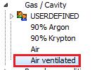
11.1Aired interstice
Air spaces that are connected with outside or inside air can be pasted from the master data area. Thereby “air ventilated outside” describes a building component layer with the air intake from outside and the air outtake outwards.
“Air ventilated inside” describes a building component layer with air intake from inside and air outtake inwards (The procedure described in EN 13363-2 are not taking into account a convection caused by wind pressure).
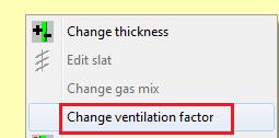
11.1.1 Change ventilation factor
|
|
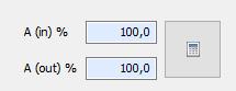
To change the ventilation factor of an interstice, you mark it and choose the point “change ventilation factor” in the context menu (right-click). In the following dialogue you can state the aperture ratios Ain und Aout.
|
|
|
Using the button
. |
|
|
|
11.1.2 Explanations for the ventilation factor
The aperture ratio ![]() is the relation
is the relation ![]() to the cross sectional area
to the cross sectional area ![]()
![]() *
100 ≤ 100; 100 [%]
*
100 ≤ 100; 100 [%]
With: ![]()
![]()
The opening ratio ![]() is the relation
is the relation ![]() to the cross sectional area
to the cross sectional area ![]()
![]() *
100 ≤ 100; 100 [%]
*
100 ≤ 100; 100 [%]
With: ![]()
![]()
|
|
For asymmetric opening distributions from the top to the bottom there has to be made realistic assessments. |
Please note
EN 13363-2, attachment B describes this procedure for the “estimating” of convection currents at the calculation. It is believed that Al, Ar and Ah preferably exist homogeneous about the height H.
11.1.3 Mechanical ventilation
1. Selection of the ventilated gap
2. Mark the ventilated layer in the editor and right mouse
-> „Change ventilation level“
3. Setting the ventilation type and the direction
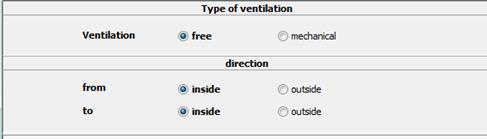
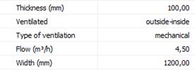
4. Information on the technical data
Free ventilation
è Opening Ain und Aout
è
Manual input or calculation
with ![]()
Mechanical ventilation
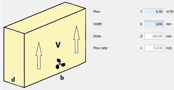
è Volume flow of mechanical ventilation in m3/h
è Width of the gap in mm
è Thickness of the intermediate space and the resulting flow velocity (m/s) for information
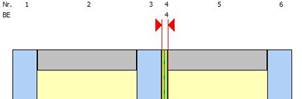
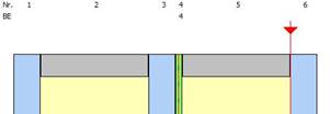
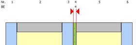
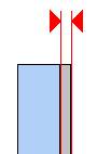
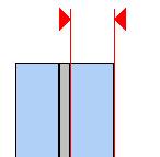
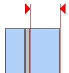
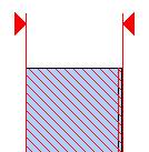
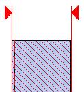
Presentation in the editor an expression
Display in layer structure
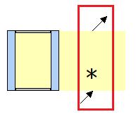
è Arrow at the bottom for outflowing air
è Arrow at the top for the direction of outflowing air
è
Symbol ![]() for mechanical ventilation;
missing with free ventilation
for mechanical ventilation;
missing with free ventilation
Display in the layer info (editor)
Extension in the print
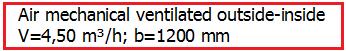
![]()
|
|
Incoming air from |
Outgoing air |
Ventilation factor gv to the inside |
|
|
inside |
inside |
> 0 |
|
|
outside |
outside |
= 0 |
|
|
inside |
outside |
= 0 |
|
|
outside |
inside |
> 0 |
11.2Assembly in the SZR
In the master data area you have different surface materials and slats available. These can be directly dragged to an existing space between the gas.
|
|
For pasting in a space between the gas simply drag the material of choice with pressed left mouse button (from master data or insertion point) to the requested interstice until a red rectangular appears.
Then drop the mouse button. Subsequently you will be asked to quote a ventilation factor.
The pasting of the surface material splits the gas-filled compartment in two symmetric bound together gas-filled compartments that can be adjusted afterwards. At the first indication of the ventilation factor, this one will be undertaken for both gas-filled compartments.
Please note: When gas-filled compartment thicknesses are changed afterwards, As. changes, meaning the ventilation factor can possibly change and eventually has to be adjusted afterwards. Please do not forget that both gas-filled compartments have to be considered separately and the change of the ventilation factor in one gas-filled compartment will not be undertaken for the other ones automatically. |
11.3Change boundary condition
In the master data area you find different climatic boundary conditions according to EN 13363-2 and ASHRAE. For new structures there will be standardly preallocated “EN 13363-2 reference”.
|
|
The boundary conditions for simulating the thermal behavior can be selected by double-clicking.
The sketch bottom left shows which boundary condition you chose. |
Additionally you can define proper boundary conditions.
With the interface below the new boundary conditions will be settled:
11.4Create slat (Slat module)
1. Click on
2. With the following interface the slat data will be determined:
3. Enter fraction of direct radiation:
Generally, a fraction of 85% of direct radiation is used for calculation, according to the specification in EN ISO 52022-3. If other fractions of direct and diffusive irradiation are required, the setting can be edited, deviating from the standard.
4. Selection of the plain material:
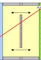
5. Defining of the slat geometry and angle
The slat geometry is defined by slat width l, center distance d, slat tilt α and sun height angle h (left sketch).
According to EN ISO 52022-3, direct sun
irreadiation into the room is not allowed
(right sketch X).
The geometry parameters l, d, α und h have tob e chosen in a way to prevent direct sun irradiation (middle sketch √ ).
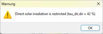
When direct sun irradiation occurs, WINSLT shows a warning. The slat geometry has to be adjusted:
6. Saving the slat with “OK”.
7. The new slat now appears in the tree
11.5Silkscreen
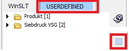
11.5.1 Generate silkscreen glass
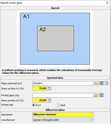
When choosing “generate silkscreen glass” silkscreen glasses can be generated by reference to the spectral data of the unprinted and printed surface. By double-clicking on an entry an appropriate dialogue opens up.
Spectral data
![]() Open importfile
Open importfile
For further information see chapter Import spectral data
![]() Product
from database
Product
from database
![]() Basic glass from database
Basic glass from database
è For the unprinted and printed glass area you can state amounts in %.
Silkscreen glass
Here you can denominate the silkscreen glass. By clicking on “OK” the data of the silkscreen glass will be calculated and the glass appears at the user-defined data in the tree
11.5.2 Silkscreen glass in VSG
The calculation of a layered structure of screen-printed glass + PVB + base glass is not permitted. To be able to calculate screen-printed glass in laminated safety glass anyway, proceed as follows:
1. Import printing as coating
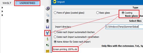
2. Save VSG with printing as product
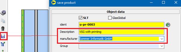
3. Save VSG without printing as product
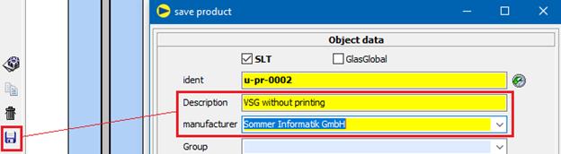
4. Generate screen printing glass for desired degree of printing
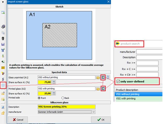
5. Calculation for partially printed VSG
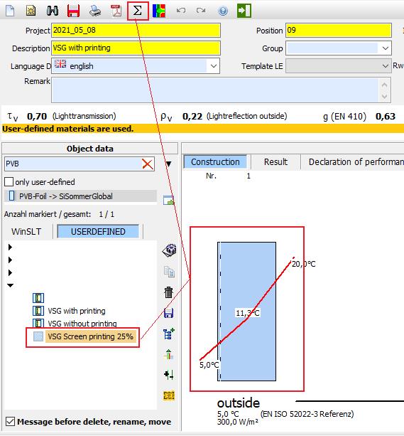
12 Import spectral data
Spectral data can be imported in form of an Excel chart.
Please note:
For the import you require the absolute values (not in percent) of the transmission and of the reflection of the front and back for the wavelength range from 250 to 2.500 nm in 2 nm, 5 nm or 10 nm steps.
Additionally the effective emissivities of both surfaces are required.
12.1Structure of an import file
File format is Excel.
In the installation directory in the folder “importmuster” you find a sample
Mandatory fields are constituted red hereafter:
|
Tools |
Value |
Value2 |
||
|
Wavelength Units |
nanometers |
|||
|
Thickness |
4 |
|||
|
Conductivity |
1 |
|||
|
IR Transmittance |
0 |
|||
|
Normal Emissivity, front back |
0,837 |
0,837 |
||
|
Product Name |
Sample product |
|||
|
Manufacturer |
Sample producer |
|||
|
Coated Side |
Neither |
|||
|
Group |
Security glass |
|
|
|
|
Minimum glass thickness |
4 |
|||
|
Slat material |
0 |
|||
|
Monolithic not usable |
0 |
|||
|
Only between gas and gas |
0 |
|||
|
Slat width |
10 |
|||
|
Axial distance |
50 |
|||
|
Slat inclination |
20 |
|||
|
Sun’s altitude |
45 |
|||
|
Hint |
|
|||
|
Spectral data |
wl |
tau |
rho |
rho' |
|
250 |
0,006 |
0,097 |
0,09 |
|
|
… |
.. |
… |
… |
|
|
…. |
… |
… |
… |
|
|
2500 |
0,9 |
0,03 |
0,04 |
|
12.2Field definition
|
|
Tools |
Value |
Value2 |
|
||||
|
|
Wavelength Units |
nanometers |
|
|||||
|
|
Mandatory field: |
Yes |
||||||
|
|
Description: |
This field quotes the unit of the wavelength |
||||||
|
|
Possible values: |
Nanometers Micrometers
|
||||||
|
|
Tools |
Value |
Value2 |
|
||||
|
|
Thickness |
4 |
|
|||||
|
Mandatory field: |
Yes |
|||||||
|
Description: |
This field quotes the thickness (mm) of the material |
|||||||
|
Possible values: |
The value must be >0 |
|||||||
|
|
Tools |
Value |
Value2 |
|
|
|
|
Conductivity |
1 |
|
||
|
Mandatory field: |
Yes |
||||
|
Description: |
This field quotes the thermo conductivity (W/mK) of the material |
||||
|
Possible values: |
The value must be >0 |
||||
|
|
Tools |
Value |
Value2 |
|
||||||||||
|
|
IRTransmittance |
0 |
|
|||||||||||
|
Mandatory field: |
No |
|||||||||||||
|
Description: |
This field quotes the transmission in the distant infra-red area |
|||||||||||||
|
|
|
|||||||||||||
|
Tools |
Value |
Value2 |
|
|||||||||||
|
Normal Emissivity, front back |
0,89 |
0,89 |
|
|||||||||||
|
Mandatory field: |
Yes |
|||||||||||||
|
Description: |
States the normal emissivity at the front and at the back, whereby “Value” defines the front and “Value2” quotes the back |
|||||||||||||
|
Possible values: |
Must be between 0 and 1 |
|||||||||||||
|
|
|
|||||||||||||
|
Tools |
Value |
Value2 |
|
|||||||||||
|
Product Name |
Sample product |
|
||||||||||||
|
Mandatory field: |
Yes |
|||||||||||||
|
Description: |
Denomination of the material |
|||||||||||||
|
|
|
|||||||||||||
|
Tools |
Value |
Value2 |
|
|||||||||||
|
Manufacturer |
Sample producer |
|
||||||||||||
|
Mandatory field: |
Yes |
|||||||||||||
|
Description: |
Denomination of the producer |
|||||||||||||
|
|
|
|||||||||||||||||
|
Tools |
Value |
Value2 |
|
|||||||||||||||
|
Coated Side |
Neither |
|
||||||||||||||||
|
Mandatory field: |
Yes |
|||||||||||||||||
|
Description: |
Type of coating. |
|||||||||||||||||
|
Possible values: |
Neither: No coating Front: Front is coated Back: Back is coated
|
|||||||||||||||||
|
Tools |
Value |
Value2 |
|
|||||||||||||||
|
Group |
Security glass |
|
||||||||||||||||
|
Mandatory field: |
No |
|||||||||||||||||
|
Description: |
For assembly in the material tree below the producer |
|||||||||||||||||
|
|
|
|||||||||||||||||
|
|
Tools |
Value |
Value2 |
|
||||||||||||||
|
|
Minimum glass thickness |
0 |
|
|||||||||||||||
|
Mandatory field: |
No |
|||||||||||||||||
|
Description: |
When specific coatings require a minimum glass thickness, it can be defined here. Then it is not possible to undercut this minimum glass thickness. |
|||||||||||||||||
|
|
|
|||||||||||||||||
|
Tools |
Value |
Value2 |
|
|||||||||||||||
|
Slat material |
0 |
|
||||||||||||||||
|
Mandatory field: |
No |
|||||||||||||||||
|
Description: |
Surface material is solely usable for slat |
|||||||||||||||||
|
Possible values: |
0 = No; 1 = Yes |
|||||||||||||||||
|
|
|
|||||||||||||||||
|
Tools |
Value |
Value2 |
|
|||||||||||||||
|
Monolithic not usable |
0 |
|
||||||||||||||||
|
Mandatory field: |
No |
|||||||||||||||||
|
Description: |
It is not allowed to use material monolithic |
|||||||||||||||||
|
Possible values: |
0 = No; 1 = Yes |
|||||||||||||||||
|
|
|
|||||||||||||||||
|
Tools |
Value |
Value2 |
|
|||||||||||||||
|
Only between gas and gas |
0 |
|
||||||||||||||||
|
Mandatory field: |
No |
|||||||||||||||||
|
Description: |
It is only allowed to use it between gas and gas |
|||||||||||||||||
|
Possible values: |
0 = No; 1 = Yes |
|||||||||||||||||
|
Tools |
Value |
Value2 |
|
|||||||||||||||
|
Slat width |
10 |
|
||||||||||||||||
|
Mandatory field: |
No |
|||||||||||||||||
|
Description: |
Only necessary for slats. Width of the slat in mm |
|||||||||||||||||
|
Possible values: |
Value must be bigger than 0 |
|||||||||||||||||
|
Tools |
Value |
Value2 |
|
|||||||||||||||
|
Axial distance |
50 |
|
||||||||||||||||
|
Mandatory field: |
No |
|||||||||||||||||
|
Description: |
Only necessary for slats. Axial distance between slats in mm |
|||||||||||||||||
|
Possible values: |
Value must be bigger than 0 |
|||||||||||||||||
|
|
|
|||||||||||||||||
|
Tools |
Value |
Value2 |
|
|||||||||||||||
|
Slat inclination |
20 |
|
||||||||||||||||
|
Mandatory field: |
No |
|||||||||||||||||
|
Description: |
Only necessary for slats. Inclination of the slat in ° |
|||||||||||||||||
|
Possible values: |
Value must be between 0 and 90 |
|||||||||||||||||
|
|
|
|||||||||||||||||
|
Tools |
Value |
Value2 |
|
|||||||||||||||
|
Sun’s altitude |
45 |
|
||||||||||||||||
|
Mandatory field: |
No |
|||||||||||||||||
|
Description: |
Only necessary for slats. Sun’s altitude / Angle of incidence in ° |
|||||||||||||||||
|
Possible values: |
Value must be between 5 und 85 |
|||||||||||||||||
|
|
|
|||||||||||||||||
|
Tools |
Value |
Value2 |
|
|||||||||||||||
|
Hint |
Combination layer on # 2; substrate thicknesses: normally: 6, 8, 10 & 12 mm |
|
||||||||||||||||
|
Mandatory field: |
No |
|||||||||||||||||
|
Description: |
Random text information can be lodged here. This one appears in the program and in the print as hint.
|
|||||||||||||||||
|
|
Spectral data |
wl |
tau |
rho |
rho' |
|
||||||||||||
|
|
250 |
0,006 |
0,097 |
0,09 |
|
|||||||||||||
|
|
255 |
0,007 |
0,094 |
0,089 |
|
|||||||||||||
|
|
260 |
0,008 |
0,093 |
0,089 |
|
|||||||||||||
|
|
265 |
0,009 |
0,091 |
0,088 |
|
|||||||||||||
|
|
… |
… |
… |
… |
|
|||||||||||||
|
|
… |
… |
… |
… |
|
|||||||||||||
|
|
2500 |
0,9 |
0,03 |
0,04 |
|
|||||||||||||
|
Mandatory field: |
Yes |
|||||||||||||||||
|
Description: |
Here the transmission, reflection front and reflection back for the wavelength ranges from 250 to 2500 are quoted continuously. There can be 1 nm or 2 or 5 or 10 nm steps. At the import you interpolate here. |
|||||||||||||||||
|
Possible values: |
tau + rho < 1 and tau + rho‘ < 1 |
|||||||||||||||||
12.3Accomplish import
1. Start the import pushing the button “data import”
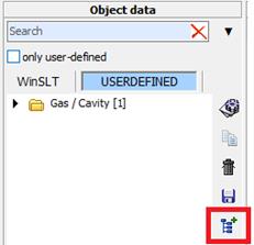
2. In the following window the choice of a directory is made pushing
the button ![]()
The settings are saved for each editor
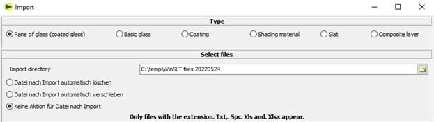
Delete file automatically after import
The file is deleted after import
Move file automatically after import
The file is moved to the specified directory after import.
No action for file after import
The file is left in its original location.
3. Defining of the type of material
a. Pane: Import as product
b. Basis glass: Uncoated glass
c. Coating: Import of a coated glass. Thereby the indication of the uncoated basis glass is necessary.
d. Surface material: Staple for the slat module
e. Slat: measured spectral data of slats
4. Marking of the files that have to be imported
5. Confirm the dialogue with “OK”.
6. Check the imports in the following window (appears per file):
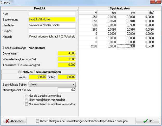
7. The imported materials appear in the tree at the selected type under User-defined.
13 Extractor (Addon)
13.1General
In the add-on “Extractor” spectral data sets can be “subtracted” (extracted) for the import into the material database.
The add-on is only available after an appropriate activation:
Here the following options are available:
· Coating to air/gas existing of a coated glass
· Composite layerextractedfrom LSG
· Coating to a composite layerextractedfrom LSG
· Waeve between composite layers extractedfrom LSG
13.2Accomplish import
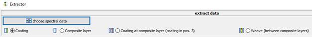
13.2.1 Set spectral data
Selection of the file with the spectral data from that the import data shall be extracted pushing the button “choose spectral data”:
![]()
This file applies to the following preconditions
ØWIS format (*.spc, *.txt) or Excel-file with predefined structure
ØExtracting of coating (to air):
o Coated glass
o Only one site coated
o Position of the coating "front" or "back"
o Only one pane -> no LSG
o Related basis glass must be already lodged in the database
ØExtracting of composite layer
o LSG with two panes
o Only one composite layer
o No coating
o Both panes consist of the same glass
o Random pane thicknesses
o Related basis glass must be already lodged in the database
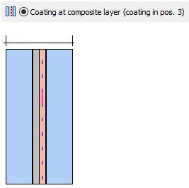
ØExtracting of coating to composite layer
o LSG with two panes
o Only one composite layer
o Coating compelling on position 3
o Both panes consist of the same glass
o Random pane thicknesses
o Related basis glass and related composite layer must already exist in the data base
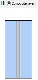
13.2.2 Selection of the extraction method
|
|
|
|
|
. |
|
|
13.2.3 Indication of the coating thicknesses
Depending on the extraction method the following coating thicknesses have to be quoted here:
![]()
ØExtracting of coating (to air):
o No specification required
o Thicknesses will be ascertained of the selected file and the basis glass
ØExtracting of composite layer
o Glass thicknesses for both panes of the LSG
ØExtracting of coating to composite layer
o Glass thicknesses for both panes of the LSG
o Additional thickness of the composite layer
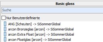
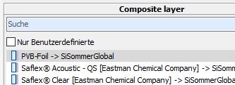
13.2.4 Basis glass and composite layer (only when coating to composite layer)
For all extracting methods the basis glass used in the spectral data must be stated.
For “coating to composite layer ” the used composite layer has to be quoted additionally.
The selection of the correct glass resp. the correct composite layer cannot be checked by the program and therefore the user is the one who is solely responsible.
|
|
|
|
To choose the basis glass you click on the appropriate entry in the list -> search using field “Search”
|
To choose the composite layer you click on the appropriate entry in the list -> search using field “Search” |
13.2.5 Indication to core data of the coating resp. composite layer
After choosing the spectral data the data will be preallocated from the file as far as practicable (denomination, manufacturer etc.).
The material will be saved with the typed in core data in the material database.
13.2.6 Accomplish calculation
The button “Calculate” accomplishes the extraction.
Hereto subsequently there will be displayed a report.
Hereto you please take into account chapter “10.3 Protocol extractor”.
|
|
13.2.7 Accomplish import
The button “Import” saves the extracted data in the database.
![]()
The coating resp. composite layer can be used in the SLT editor now.
When you consecutively import several coatings, all coatings are quoted under “imported spectral data” until you leave the dialogue.
Here, the imported materials can be deleted again, too:
Thereto you mark the appropriate entry in the list and
click on the button![]() .
.
13.3Protocol extractor
For each extraction procedure a protocol is generated.
All errors, warnings and notes that occur during the calculation are contained in the protocol.
The declarations are made for the tabs 1, 2 and 3 according to EN 410 per wavelength.
Pushing the button “Save Protokoll” the appropriate text file can be saved.
At each import procedure the related protocol will be saved automatically under the following file name:
Name of the original spectral file + “_log.txt”.
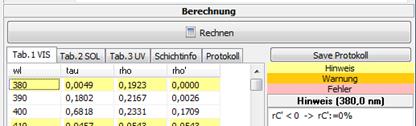
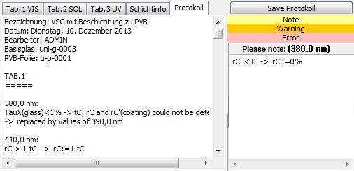
On the tabs “Tab.1”, “Tab.2” und “Tab.3” some information to the particular wavelengths are displayed.
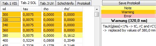
· OK (white)
· Note (yellow)
-> Values have been automatically corrected during the calculation, e.g. when a calculation was not possible because of an insufficient transmission
· Warning (orange)
-> Not calculable values were replaced by the values below resp. above (edge upstairs resp. downstairs) or defined by interpolation (interim values)
· Error (red)
-> Values could not be defined even by interpolation. An import is not possible.
A click on a certain wavelength displays the related information right beside.
14 ASHRAE
14.1General
ASHRAE is a professional association of all those working in the heating, cooling, ventilation and air conditioning industry in the USA. The association also specifies how to calculate according to ISO 15099. This standard provides in part two ways to determine characteristic values. ASHRAE then specifies which method is to be used.
In the add-on "ASHRAE", all radiation-physical and thermal parameters can be calculated according to the calculation basis of ISO 15099 and the specifications of ASHRAE. The program structure remains unaffected.
The add-on is only available after corresponding activation:
14.2Boundary conditions
In addition to specifying the calculation basis, ASHRAE also specifies boundary conditions. They are differentiated into summer and winter boundary conditions, whereby the winter boundary conditions must be used to determine the U-value and the summer boundary conditions to determine the g-value (SHGC value). The boundary conditions can be selected under the master data Boundary Condition.
U-value calculations (winter): g-value calculations (summer):
Ti = 21°C Ti = 24°C
Te= -18°C Te = 32°C
vWind = 5,5 m/s vWind = 2,75 m/s
Tr,i = Ti Tr,i = Ti
Tr,e = Te Tr,e = Te
Is= 0 W/m² Is = 783 W/m²
14.3Emissivity
A corrected emissivity is calculated for the glass panes. The calculation basis for this is taken from NFRC100-2010.
14.4Gases
The gas properties are taken from Annex A of the NFRC 101 and mixed according to the specifications of ISO 15099.
14.5SHGC value
The SHGC value is the North American equivalent of the g-value and is calculated according to NFRC 200-2014.
![]()
![]()
14.6Printing
The term It has been adapted so that all results from the calculations and also the boundary conditions according to ASHRAE are displayed.
15 Sound database
15.1Glossary
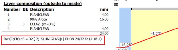
Evaluated sound insulation dimension R¬¬w
Rw is the sound reduction index of a building component, evaluated on the basis of a standard curve (to take human hearing into account).
It is given in dB.
Spectrum matching values C; Ctr
According to EN ISO 717-1, the spectrum adaptation values C and Ctr ("tr" for road traffic "traffic") denote a value in decibels that must be added to the singular Rw to take a specific sound spectrum into account.
The complete specification of the sound insulation of a component is given as follows:
Rw (C; Ctr) = 40 (-2; -5) dB
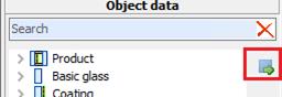
15.2Product search on the main screen
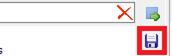
The sound database can be called up in the main mask by clicking the following button:
You will receive a list of the deposited products for sound insulation:
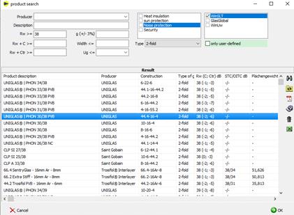
![]()
è Setting the filters and searches
è „Rw", "Rw + C >=" and "Rw + Ctr >="
The required sound insulation value is taken as the minimum value and all products with a sound insulation value higher or equal to the specification are listed..
![]()
è Shows deposited PDF, e.g. test certificate, expert opinion
è Button only available if PDF is available
![]()
è Edit product
è Only for custom products and editors is Admin
![]()
è Delete product
è Only for custom products and editors is Admin
Selection of the product
è Select the marked product by clicking "OK
è or double click on product line
è Transfer of the sound insulation values and the product name to the main mask of the editor
Sort
è When you click on a heading, the list is sorted according to the column clicked on
15.3Product search
To select a product, proceed as follows:
è Call up product search:
o WINSLT®
è The product search is displayed
è
The available functions are described under
point 2
15.4Determining Rw from database
When searching the database, the type of gas in the SDR is not taken into account.
To determine the sound insulation value for an existing glass structure from the database, proceed as follows:
è Call up product search
![]()
è
Display of the products that match the current
structure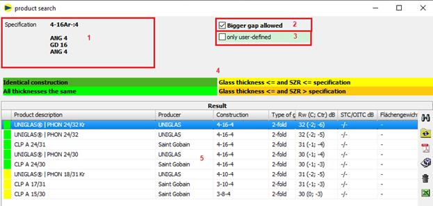
For products to be displayed with a sound insulation film (e.g. "..|PHON..NC"), the design must also include a sound insulation film (e.g. Trosifol® SC Monlayer or Multilayer) in the specification.
1 Default = current structure
2 Larger SDR allowed: products with a larger SDR (orange) are also displayed. Check is off by default because the comparison is on the insecure side.
3 User-defined only displays only products that have been saved by the user.
4 Legendfor the individual colors
The nature of the gas in the SDR is not taken into account.
![]()
The structure is identical to the specification, i.e. all thicknesses (glass, SDR and composite layers) are the same.
![]()
All thicknesses (glass and SDR) match. The composite layers are not taken into account. For laminated safety glass, monolithic panes of the same thickness are also determined without taking the composite layers into account.
Only monolithic panes of the same thickness are determined for monolithic panes.
![]()
At least one glass thickness or SDR is less than the specification. The composite layers are not taken into account.
![]()
At least one SDR is greater than the specification and the glass thicknesses are less than or equal to the specification. The composite layers are not taken into account.
1 Search result
è Select a product and confirm with OK
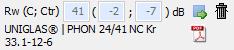
è
Existing values can be deleted with the button![]()
è
A manual entry is made directly into the input
fields: ![]()
15.5Printout
è Result
Rw is only shown on the printout if a value has been stored:
Declaration of performance![]()
è CE
![]()
15.6Define product
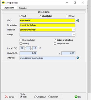
User-defined products are stored as follows:
è Define pane structure
è Save the current slice structure as a product:
o WINSLT®
è Enter product data
16 Vacuum insulation glazing (Add-on)
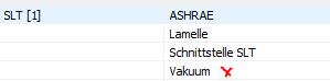
16.1Addon, Activation
The calculation for vacuum insulating glazing (VIG) is only available if the add-on "Vacuum" has been activated for WINSLT®:
A new activation of the license may be required.
16.2Insert vacuum
1. Click on
2. either by double-clicking or by dragging to the editor
3. heat transmission coefficient for supports hp and residual gas ha
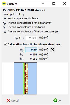
hp + ha Input thermal transmittance coefficient for supports hp and residual gas ha
Ug ![]() Determination of hp + ha using the Ug value
Determination of hp + ha using the Ug value
è Only available with valid layer structure
è Determination from the displayed structure
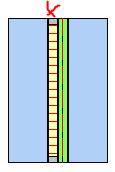
4. Confirm with OK. The vacuum is inserted as a gap in the structure.
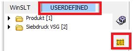
5. a user-defined entry is created in the tree for later use
![]()
16.3Change vacuum
1. mark vacuum in editor
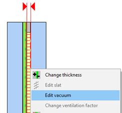
2. right mouse button
3. "Change vacuum" menu
4. adjust value for hp + ha
5. confirm with OK
16.4Technical details
The calculation is based on ISO/FDIS 19916-1:2018, Annex C:
hv = hp + hr + ha
hv Heat transmission coefficient vacuum [W/(m²K)]
vacuum space conductance
hp Thermal transmittance coefficient of the supports [W/(m²K)].
thermal conductance of the pillar array
ha Heat transmission coefficient of the low-pressure gas [W/(m²K)].
thermal conductance of the low pressure gas
· hg (cable) = hc (convection) = 0
· hr (radiation) remains unchanged compared to "normal" air spaces
· Consider in the calculation according to EN 673 and EN 52022-3
17 Products no longer produced
Previously, spectral data for products no longer in production were deleted from the database. From now on these will remain in the database, but will be marked accordingly.
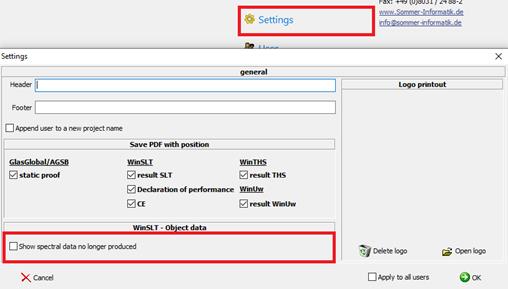
17.1Settings
To display spectral data that is no longer produced, the display must be enabled in the settings. By default, the setting is disabled.
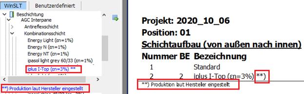
17.2Display and printout
Relevant layers are marked accordingly in the tree and in the printout:
18 CIE L*a*b* (DIN EN ISO 11664-4)
18.1Settings
18.2Output
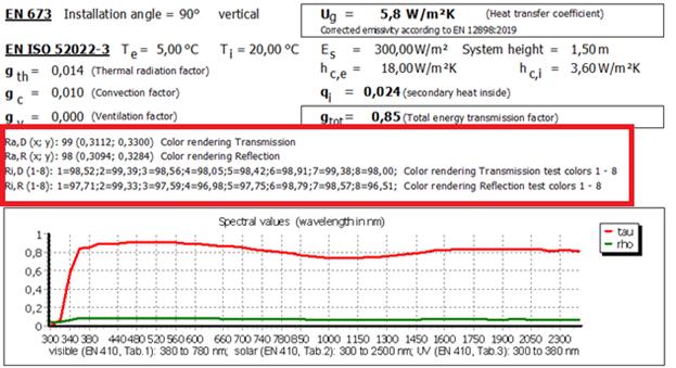
19 Extension of colour rendering index (EN 410)
è Colour rendering index for the respective test colour
è Colour rendering index for transmission (Ra,D) and reflection (Ra,R) according to DIN EN 410
19.1Settings
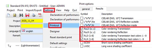
19.2Output
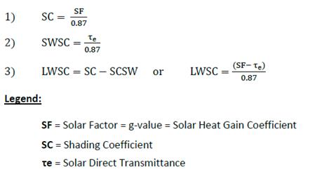
20 SCSW and LWSC
Two additional shading coefficients were implemented for the UK market:
SCSW = Short wave shading coefficient
LWSC = Long wave shading coefficient
20.1Settings
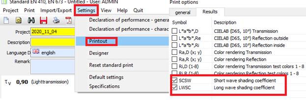
20.2Output
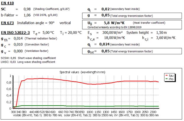
20.3Calculation
21 Downward heat flow
21.1Input
Until now, the installation angle was limited to values between 0° and 90°:
è horizontal, heat flow upwards
![]()
è vertical
![]()
The input was extended to values from >90° to 180°:
è horizontal, heat flow downwards
![]()
21.2Calcultion
21.2.1 Internal convective heat transfer coefficient hci
Note
For calculation according to EN ISO 52022-3, the internal convective heat transfer coefficient hci must be manually adjusted in the boundary conditions.
For DIN EN 673 this is done automatically according to the following description.
So far the following values have been used in WINSLT®:
è Installation angle = 0° (heat flow upwards)
hci = 5,0 W /(m²K) according to DIN EN ISO 6946 (A.4)
è
Installaiton angle = 90°
hci = 3,6 W /(m²K) according to DIN EN ISO 673 (7.2)
è intermediate values are interpolated
For the heat flow downwards the calculation was extended as follows:
è Installation angle = 180°(heat flow downwards)
hci = 0,7 W /(m²K) according to DIN EN ISO 6946 (A.4)
è Values between 90° and 180° are interpolated
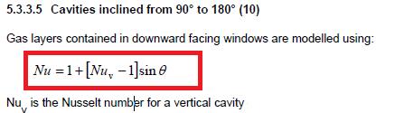
21.2.2 Nusselt number
The existing determination of the Nusselt number (calculation according to EN ISO 52022-3 and DIN EN 673) was extended by the determination for an installation angle > 90° and ≤180° based on ISO 15099 as follows
Nu = 1 + (Nu90 - 1) * sin(winkel)
Nu90 Nusselt number for 90° according to DIN EN 673 (6)
sin(90°) = 1 -> Nu = Nu¬90
sin(180°) = 0 -> Nu = 1
21.3Normative Backround
21.3.1 DIN EN 673
![]()
21.3.2 ISO 15099
22 Temperature display
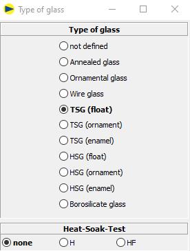
23 FTG-H and -HF
1. Designation FTG
o Without addition
o or with addition H (hot storage)
o or with addition HF (hot storage and external monitoring)
2. Default: none
3. Only visible for FTG (float), FTG (ornament) and FTG (enamel)
4. Appears in the designation on the printout
On the printout:
![]()
24 Colour for glass types
In the starter in the settings, a colour can be defined for each glass type.
Default: light blue.
- Previous settings on the General tab
- New tab "Colours“
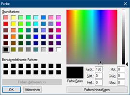

The colours appear in the respective programme modules and on the printout.
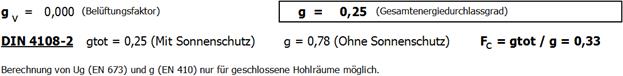
25 Fc-value (DIN 4108-2)
Reduction factor of the sun protection (FC) according DIN 4108-2:
FC = gtot / g
gtot total energy transmittance with sunscreen
g total energy transmittance without sunscreen
The following procedure applies to determining the FC value:
1. Start module „WinSLT Experte“
2. Input of the structure with sun protection device
3. Activate FC-value determination
![]()
è Hook is only available for structures with sunshades.
4. The FC-value is also specified on the result expression:
![]()
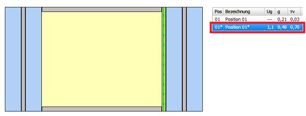
5. By saving, the structure is automatically generated without sun protection and saved in a separate position, marked with „*“.
The position without sun protection(*) is automatically adjusted when the position is changed with sun protection.
If the original position is deleted, the position without sunshade (*) is outomatically deleted.
è Position with sunscreen
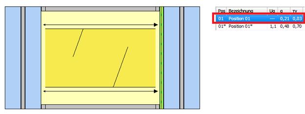
è Position without sunscreen